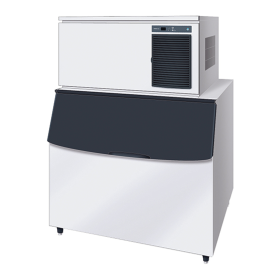
Hoshizaki IM-240DNE Service Manual
Modular cuber
Hide thumbs
Also See for IM-240DNE:
- Installation manual (88 pages) ,
- Instruction manual (26 pages) ,
- Instruction manual (68 pages)

Subscribe to Our Youtube Channel
Related Manuals for Hoshizaki IM-240DNE


Summary of Contents for Hoshizaki IM-240DNE
- Page 1 MODULAR CUBER IM-240DNE(-C) IM-240DWNE(-C) IM-240DWNE-R452 IM-240DSNE IM-240XNE(-C) IM-240XWNE(-C) SERVICE MANUAL IM-240XWNE-R452 IM-240XSNE IM-240ANE IM-240AWNE E1CK-810 (113021)
-
Page 2: Table Of Contents
2. WATER VALVE ------------------------------------------------------------------------------------ 26 3. WATER-COOLED CONDENSER ------------------------------------------------------------ 27 4. ICEMAKING WATER SYSTEM --------------------------------------------------------------- 28 V. TECHNICAL INFORMATION --------------------------------------------------------------------- 31 1. WATER CIRCUIT AND REFRIGERANT CIRCUIT --------------------------------------- 31 [a] IM-240DNE/XNE, IM-240DNE-C/XNE-C, IM-240ANE ----------------------------- 31 [b] IM-240DWNE(-R452)/XWNE(-R452), IM-240DWNE-C/XWNE-C, IM-240AWNE---------------------------------------------------------------------------------- 32 [c] IM-240DSNE/XSNE+URC-240C-E-4 --------------------------------------------------- 33... - Page 3 2. WIRING DIAGRAM ------------------------------------------------------------------------------ 34 [a] IM-240DNE(-C)/XNE(-C), IM-240DWNE(-C/-R452)/XWNE(-C/-R452), IM-240ANE/AWNE --------------------------------------------------------------------------- 34 [b] IM-240DSNE/XSNE+URC-240C-E-4 --------------------------------------------------- 35 3. PERFORMANCE DATA ------------------------------------------------------------------------- 36 [a] COPELAND COMPRESSOR ------------------------------------------------------------- 36 [b] SECOP (DANFOSS) COMPRESSOR -------------------------------------------------- 39 VI. SERVICE DIAGNOSIS --------------------------------------------------------------------------- 44 1. ERROR CODE INDICATION ------------------------------------------------------------------ 44 2.
-
Page 4: Specifications
I. SPECIFICATIONS 1. DIMENSIONS/SPECIFICATIONS [a] IM-240DNE (Air-cooled) -
Page 5: [B] Im-240Dne
[b] IM-240DNE-C (Air-cooled) -
Page 6: [C] Im-240Dwne
[c] IM-240DWNE (Water-cooled) -
Page 7: [D] Im-240Dwne
[d] IM-240DWNE-C (Water-cooled) -
Page 8: [E] Im-240Dwne-R452
[e] IM-240DWNE-R452 (Water-cooled) -
Page 9: [F] Im-240Ane
[f] IM-240ANE (Air-cooled) -
Page 10: [G] Im-240Awne
[g] IM-240AWNE (Water-cooled) -
Page 11: [H] Im-240Dsne
[h] IM-240DSNE (Remote Air-cooled) -
Page 12: [I] Urc-240C-E-4 (Condenser Unit)
[j] URC-240C-E-4 (Condenser Unit) -
Page 13: General Information
II. GENERAL INFORMATION 1. CONSTRUCTION [a] IM-240DNE/XNE, IM-240DNE-C/XNE-C (Air-cooled) Top Panel Louver, Air Filter Front Panel Bin Door Handle Evaporator Water Plate Water Valve Bin Control Switch Hot Gas Valve Water Tank Power Cord Pump Motor Control Box (B) Compressor... -
Page 14: [B] Im-240Dwne(-R452)/Xwne(-R452), Im-240Dwne-C/Xwne-C
[b] IM-240DWNE(-R452)/XWNE(-R452), IM-240DWNE-C/XWNE-C (Water-cooled) Top Panel Front Panel Bin Door Handle Evaporator Water Plate Water Valve Bin Control Switch Hot Gas Valve Water Tank Power Cord Pump Motor Water Regulator Compressor Drain Pan Actuator Motor Control Box (A) Control Box (B) Water-Cooled Condensor... -
Page 15: [C] Im-240Ane
[c] IM-240ANE (Air-cooled) Top Panel Power Cord Nameplate Louver, Air Filter Front Panel Bin Door Water Valve Handle Drain Pipe Rear Front Compressor Hot Gas Valve Fan Motor Control Box Air-Cooled Condenser Evaporator Water Plate Water Tank Actuator Motor Pump Motor Bin Control Switch Drain Pan Front... -
Page 16: [D] Im-240Awne
[d] IM-240AWNE (Water-cooled) Top Panel Power Cord Nameplate Front Panel Cooling Water Inlet Bin Door Cooling Water Outlet Handle Water Valve Drain Pipe Rear Front Water-Cooled Condenser Hot Gas Valve Water Regulator Control Box Compressor Evaporator Water Plate Water Tank Actuator Motor Pump Motor Bin Control Switch... -
Page 17: [E] Im-240Dsne
[e] IM-240DSNE (Remote Air-cooled) Top Panel Front Panel Bin Door Handle Water Valve Front Hot Gas Valve Evaporator Power Fan Motor Cord Wiring Cord Pump Motor Access Valve Actuator Motor Control Box Dryer Compressor Starting Device Front Drain Pan Water Tank Receiver Tank Bin Control Drain Pipe... -
Page 18: [F] Urc-240C-E-4
[f] URC-240C-E-4 (Condenser Unit) Top Panel Unit Cover Service Valve Cable Clamp Condenser CP Regulator Fan Motor Control Box... -
Page 19: Controller Board
2. CONTROLLER BOARD Note: Refer to the controller board service manual. IMPORTANT If receiving a service call, ask the user to turn off the power to the icemaker and turn it on again, while watching the icemaker. This will reset the controller, and in some cases normal operation will resume. -
Page 20: [A] Controller Board Layout
[a] CONTROLLER BOARD LAYOUT Main Board Sub Board Combination... -
Page 21: [B] Input/Output Layout
[b] INPUT/OUTPUT LAYOUT Hall IC Input XA Connector (4P) Bin Control Switch / Pressure Switch / Condenser Thermistor Input XA Connector (6P) Cube Control Thermistor Input XA Connector (2P) 7-Segment Double- Digit Display Data Input/Output PA Connector (8P) Reset Button 10.5V AC Input VH Connector (2P) Close Button Open Button... -
Page 22: [C] Before Checking Controller Board
[c] BEFORE CHECKING CONTROLLER BOARD Check the power source voltage and the components as shown in the table below. Component Procedure Normal 1. Thermistor CAUTION 5 -7 kilohms (on evaporator) Thermistor sensor part is fragile, glass sealed. Handle with care. Holder * Disconnect the connector CN13 on Screw... -
Page 23: Operating Instructions
III. OPERATING INSTRUCTIONS WARNING 1. This icemaker is designed to produce and store edible ice. To keep the icemaker hygienic: * Wash your hands before removing ice. Use the plastic scoop provided (accessory). * The storage bin is for ice use only. Do not store anything else in the bin. -
Page 24: Preparing The Icemaker For Long Storage
4) The following should occur in sequence: a) Hot gas valve will open. b) Compressor will start. c) Water pan will fully open. d) Water valve will open. e) Water pan will start to close (hot gas valve closed). f) Water pan fully closed - pump motor will start. g) Water valve will close. -
Page 25: Bin Control
10) Replace the panels in their correct positions. 11) Replace the inlet hose in its correct position. 3. BIN CONTROL Bin control switch is mounted on the upper side of the storage bin. This switch will turn off the unit automatically when the storage bin is full of ice. -
Page 26: [B] Removal
[b] REMOVAL BRACKET COVER Push the two pawls and remove the bracket cover. SWITCH Pull out the switch, holding the rubber leads cap. Handle with care. SWITCH ACTUATOR Insert a flat blade screwdriver and wrench it slightly to pull out the switch actuator. Handle with care to prevent damage to the cam surface of the actuator. -
Page 27: Maintenance Instructions
[3] Storage Bin Interior Cleaning/Sanitisation (Weekly) 1) Open the storage bin door, and remove all ice. Note: Hoshizaki recommends various types of storage bin for the icemaker which vary in size and design. The following instructions are therefore for general... - Page 28 5) Rinse thoroughly with fresh water and a clean cloth to wipe off the solution. Close the bin door. Note: Some solutions may cause damage to the bin liner surfaces or corrosion on the metal parts. Always rinse the sanitiser unless directed otherwise by Hoshizaki guidelines. [4] Air Filter (Air-Cooled Model Only) Plastic mesh air filters remove dirt or dust from the air, and keep the condenser from getting clogged.
-
Page 29: Water Valve
2. WATER VALVE 1) Unplug the icemaker or disconnect the power source. 2) Close the water supply tap. 3) Remove the top panel and front panel. 4) Disconnect the inlet hose from the water valve. 5) Remove the mesh filter from the water valve. 6) Clean the mesh using a brush. -
Page 30: Water-Cooled Condenser
3. WATER-COOLED CONDENSER Deposits inside the water circuit of the water-cooled condenser decrease cooling performance. Clean inside of the condenser by circulating a cleaning solution. 1) Prepare the following: Cleaning solution [Read and follow any instructions on label or bottle.] Pump Container for solution Hose... -
Page 31: Icemaking Water System
1. Always wear rubber gloves, eye protectors, apron, etc. for safe handling of the cleaner and sanitizer. 2. Use the cleaners and sanitizers recommended by Hoshizaki. Contact your local Hoshizaki office for further details. (The instructions below give an example of those recommended cleaners and sanitizers.) 3. - Page 32 16) Use a suitable container to dilute 44 ml of 5.25% sodium hypochlorite solution with 11.4 lit. of water. * Alternatively use the Hoshizaki recommended sanitizer as directed by the relevant instructions. 17) Close the water supply tap. Plug in the icemaker or connect the power source.
- Page 33 18) When the flush mode has started, pour the cleaning solution prepared in 16) carefully into the water tank within 60 seconds before the pump motor starts. Do not splash or spill the solution onto the other parts. 19) Circulate the sanitizing solution for 15 minutes. Push the reset switch to open the water pan.
-
Page 34: Technical Information
V. TECHNICAL INFORMATION 1. WATER CIRCUIT AND REFRIGERANT CIRCUIT [a] IM-240DNE/XNE, IM-240DNE-C/XNE-C, IM-240ANE (Air-cooled) Water Valve Expansion Valve Evaporator Thermistor Controller Board Expansion Valve Bulb Water Pan Water Pump Condenser Thermistor Hot Gas Fan Motor Valve Strainer Compressor Drier Water Circuit... -
Page 35: [B] Im-240Dwne(-R452)/Xwne(-R452), Im-240Dwne-C/Xwne-C, Im-240Awne
[b] IM-240DWNE(-R452)/XWNE(-R452), IM-240DWNE-C/XWNE-C, IM-240AWNE (Water-cooled) Water Valve Expansion Valve Evaporator Thermistor Controller Board Expansion Valve Bulb Water Pan Water Pump Pressure Water Regulating Valve Switch Condenser Drier Hot Gas Valve Strainer Compressor Water Circuit Refrigerant Circuit... -
Page 36: [C] Im-240Dsne/Xsne+Urc-240C-E-4
[c] IM-240DSNE/XSNE+URC-240C-E-4 Water Expansion Valve Valve Pressure Bulb Switch Drier Thermistor Receiver Water Pan Tank Water Pump Insulation Controller Access Board Valve Connecting Pipe Hot Gas Valve Insulation Strainer Connecting Pipe Condenser Compressor Condenser Unit Access Valve Water Circuit Refrigerant Circuit... -
Page 37: Wiring Diagram
2. WIRING DIAGRAM [a] IM-240DNE(-C)/XNE(-C), IM-240DWNE(-C/-R452)/XWNE(-C/-R452), IM-240ANE/ AWNE... -
Page 38: [B] Im-240Dsne/Xsne+Urc-240C-E-4
[b] IM-240DSNE/XSNE+URC-240C-E-4... -
Page 39: Performance Data
3mm (7mm) for -21 Ambient Temp. (°C) Model Water Temp. (°C) Cube Hole Diameter (mm) 5 (15) 5 (15) 5 (15) 5 (15) IM-240DNE Ice Production (kg/d) 230 (240) 220 (230) 200 (210) 170 (185) IM-240XNE Freeze Cycle Time (min) 16.0 (14.6) 18.2 (16.8) - Page 40 Ambient Temp. (°C) Model Water Temp. (°C) Cube Hole Diameter (mm) 5 (15) 5 (15) 5 (15) 5 (15) IM-240DWNE Ice Production (kg/d) 230 (240) 215 (225) 205 (215) 185 (200) IM-240XWNE Freeze Cycle Time (min) 17.8 (16.2) 19.2 (17.5) 20.7 (18.5) 23.1 (20.0) Defrost Cycle Time (min)
- Page 41 25.0 Ambient Temp. (°C) Model Water Temp. (°C) Cube Hole Diameter (mm) 10 (20) 10 (20) 10 (20) 10 (20) IM-240DNE-C Ice Production (kg/d) 210 (240) 190 (220) 170 (190) 150 (165) IM-240XNE-C Freeze Cycle Time (min) 18.4 (15.4) 22.5 (18.3) 25.8 (21.5)
-
Page 42: [B] Secop (Danfoss) Compressor
3mm (7mm) for -21 Ambient Temp. (°C) Model Water Temp. (°C) Cube Hole Diameter (mm) 5 (15) 5 (15) 5 (15) 5 (15) IM-240DNE Ice Production (kg/d) 230 (240) 210 (220) 190 (200) 160 (175) IM-240XNE Freeze Cycle Time (min) 15.8 (14.5) 18.7 (16.9) - Page 43 Ambient Temp. (°C) Model Water Temp. (°C) Cube Hole Diameter (mm) 5 (15) 5 (15) 5 (15) 5 (15) IM-240DNE-23 Ice Production (kg/d) 185 (230) 180 (215) 170 (195) 150 (165) IM-240XNE-23 Freeze Cycle Time (min) 14.5 (10.4) 16.3 (12.4) 18.2 (15.0)
- Page 44 Ambient Temp. (°C) Model Water Temp. (°C) Cube Hole Diameter (mm) 5 (15) 5 (15) 5 (15) 5 (15) IM-240DWNE-R452 Ice Production (kg/d) 230 (240) 215 (225) 205 (215) 185 (200) IM-240XWNE-R452 Freeze Cycle Time (min) 21.3 (20.0) 23.1 (21.3) 25.0 (22.4) 29.0 (25.1) Defrost Cycle Time (min)
- Page 45 25.0 Ambient Temp. (°C) Model Water Temp. (°C) Cube Hole Diameter (mm) 10 (20) 10 (20) 10 (20) 10 (20) IM-240DNE-C Ice Production (kg/d) 210 (240) 190 (220) 170 (190) 150 (165) IM-240XNE-C Freeze Cycle Time (min) 18.4 (15.4) 22.5 (18.3) 25.8 (21.5)
- Page 46 Suction Pressure and Evaporator Temp. 50/60Hz Ambient Temp. (°C) Model Water Temp. (°C) Suction Pressure Peak (bar) IM-240_NE Evaporator Inlet Temp. (°C) Suction Pressure Peak (bar) IM-240_NE-21 Evaporator Inlet Temp. (°C) Suction Pressure Peak (bar) IM-240_NE-32 Evaporator Inlet Temp. (°C) Note: The above data are only for reference in servicing.
-
Page 47: Service Diagnosis
VI. SERVICE DIAGNOSIS 1. ERROR CODE INDICATION * See the controller board service manual for detailed diagnosis and remedies. * The error and caution codes other than E1 and E2 are indicated as “EE” in the 7-segment display at the time of occurrence. But the error history is recorded as the actual error codes in parenthesis, and a maximum of five errors are indicated from the latest entry. -
Page 48: Error Code Indication
2. NO ERROR CODE INDICATION Problem Check Possible Cause Remedy Icemaker will Power source Turned off. Turn on. not start. Supply voltage too low. Remove cause Power failure Wait until power is resumed. Transformer Defective. Replace. Power cord Not connected properly. Reconnect. - Page 49 Problem Check Possible Cause Remedy Imperfect ice Insufficient water Water valve filter clogged. Clean. production. supply Water supply cycle too short. Extend. Water supply pressure too low. Remove cause. Water leaks from Water tank broken. Replace. water tank or Water plate broken. Replace.
-
Page 50: Adjustment
VII. ADJUSTMENT 1. EXPANSION VALVE The expansion valve is factory-adjusted. Do not adjust it except at replacement or service. Adjust the valve setting, if necessary, as follows: 1) Remove the cap nut. 2) Rotate the adjust screw by using a flat blade screwdriver. 3) Watch holes of ice cubes produced. -
Page 51: Water Regulating Valve - Water-Cooled Model Only
2. WATER REGULATING VALVE - WATER-COOLED MODEL ONLY The water regulating valve is factory-adjusted. Do not adjust it except at replacement or service. Adjust the valve setting, if necessary, as follows: 1) Attach a pressure gauge to high-side line, or prepare a thermometer to check condenser drain temperature. -
Page 52: Full Drain Flush
3. FULL DRAIN FLUSH In some hard water areas, white ice and scaling can be caused. In such case, install a filter or softener, and change the flush mode from “partial drain flush” to “full drain flush” according to the following instructions. Full drain flush –... -
Page 53: Removal And Replacement
VIII. REMOVAL AND REPLACEMENT 1. SERVICE FOR REFRIGERANT LINES [a] SERVICE INFORMATION 1) Allowable Compressor Opening Time and Prevention of Lubricant Mixture [R404A] The compressor must not be opened more than 30 minutes in replacement or service. Do not mix lubricants of different compressors even if both are charged with the same refrigerant, except when they use the same lubricant. -
Page 54: [B] Refrigerant Recovery
type copper tubes are used in the shipped units.) 7) Evacuation, Vacuum Pump and Refrigerant Charge [R404A] Never allow the oil in the vacuum pump to flow backward. The vacuum level and vacuum pump may be the same as those for the current refrigerants. However, the rubber hose and gauge manifold to be used for evacuation and refrigerant charge should be exclusively for R404A. -
Page 55: Compressor
Note: Always charge in the liquid stage, as many refrigerants are blends and vapour charging will affect the blend consistency (e.g. R404A). 7) Turn on the icemaker. Release the high-side access connector, and allow pressure in the charging line to slowly enter the low side of the system. Cap off the high- side access valve. -
Page 56: Drier
17) Replace the panels in their correct positions. 18) Plug in the icemaker or connect the power source. Note: Hoshizaki recommends that compressor starting electrics are always replaced at the same time as the compressor. 3. DRIER 1) Unplug the icemaker or disconnect the power source. -
Page 57: Expansion Valve
9) Replace the panels in their correct positions. 10) Plug in the icemaker or connect the power source. Note: Always use a drier of the correct capacity and refrigerant type. 4. EXPANSION VALVE IMPORTANT Always install a new drier every time the sealed refrigeration system is opened. -
Page 58: Evaporator
12) Replace the panels in their correct positions. 13) Plug in the icemaker or connect the power source. 5. EVAPORATOR IMPORTANT Always install a new drier every time the sealed refrigeration system is opened. Do not replace the drier until after all other repair or replacement has been made. -
Page 59: Hot Gas Valve
6. HOT GAS VALVE IMPORTANT Always install a new drier every time the sealed refrigeration system is opened. Do not replace the drier until after all other repair or replacement has been made. 1) Unplug the icemaker or disconnect the power source. 2) Remove the top, front and right side panels. -
Page 60: Water Regulating Valve - Water-Cooled Model Only
7. WATER REGULATING VALVE - WATER-COOLED MODEL ONLY [a] VALVE BODY 1) Unplug the icemaker or disconnect the power source. 2) Close the water supply tap. 3) Remove the front panel and right side panel. 4) Disconnect the flare connections of the water regulating valve. 5) Remove the valve from the bracket. - Page 61 6) Cut off the capillary tubes of the valve and high-pressure switch, using a file and pliers. Be careful not to damage the capillary tube end. 7) Disconnect the flare connections from the bracket. 8) Remove the screws and the valve from the bracket. 9) Install the new valve, and insert the capillary tubes into the copper tube.
-
Page 62: Water Pan Assembly
8. WATER PAN ASSEMBLY 1) Remove the top, front and left side panels. 2) Push the reset switch on the control box to open the water pan. 3) Unplug the icemaker or disconnect the power source. 4) Disconnect the pump motor leads in the wiring channel. 5) Remove the two extension springs from the cam arms. - Page 63 INDEX NO. DESCRIPTION Water Tank Water Plate Bracket Bracket Spring Hook Screw Pump Tubing (Suction) Pump Tubing (Discharge) Pump Motor Bracket Water Plate Overflow Pipe Thumbscrew (for Overflow Pipe) Nylon Tie O-ring Pump Motor Assembly S1 - 4 Tapping Screw Machine Screw Fig.
-
Page 64: Pump Motor
9. PUMP MOTOR 1) Unplug the icemaker or disconnect the power source. 2) Remove the top panel and front panel. 3) Disconnect the pump motor leads in the wiring channel. 4) Unscrew and remove the pump motor from the bracket. 5) Disconnect the pump suction and discharge tubings. -
Page 65: Actuator Motor
11. ACTUATOR MOTOR 1) Remove the top panel and front panel. 2) Push the reset switch on the control box to open the water pan. 3) Unplug the icemaker or disconnect the power source. 4) Remove the extension spring (actuator motor side) from the cam arm. 5) Disconnect the actuator motor leads in the wiring channel. - Page 66 7) Install the new cam in the reverse order of the removal procedure. 8) Replace the panels in their correct positions. 9) Plug in the icemaker or connect the power source. Fig. 15...
- Page 67 ICEMAKING ASSEMBLY AND CAM MECHANISM INDEX NO. DESCRIPTION Water Pan Assembly Evaporator Bolt Collar (Spacer) Bearing Actuator Motor Shaft Actuator Motor Bracket Cam Shaft Bearing Spring Pin Cam Arm (B) Cam Shaft Snap Pin Split Pin Spring Washer (A) Washer (B) Washer (C) Thermistor Holder Label (for Overflow Pipe)
-
Page 68: Controller Board
13. CONTROLLER BOARD IMPORTANT Some adjustment will be required for the controller board to fit the icemaker models. Do not repair any parts and electronic devices on the controller board in the field. Replace the whole board with a new service board. 1) Unplug the icemaker or disconnect the power source. - Page 69 Controller Board Board Support Control Box Cover Screw Fig. 16...
-
Page 70: Thermistor For Cube Control
14. THERMISTOR FOR CUBE CONTROL 1) Unplug the icemaker or disconnect the power source. 2) Remove the top and front panels. 3) R e m o v e t h e c o n n e c t o r C N13 o n t h e c o n t r o l l e r b o a r d , r e f e r r i n g t o “13. CONTROLLER BOARD”. -
Page 71: Fan Motor - Air-Cooled Model Only
15. FAN MOTOR - AIR-COOLED MODEL ONLY 1) Unplug the icemaker or disconnect the power source. 2) Remove the top, front and right side panels. 3) Disconnect the connector of the fan motor. 4) Remove the fan motor bracket and the fan motor. 5) Cut the leads of the fan motor allowing enough lead length to reconnect using closed end connectors. -
Page 72: Multi-Stack Applications
IX. MULTI-STACK APPLICATIONS The following option kits are available for multi-stack applications of IM-240DNE(-C)/ XNE(-C), IM-240DWNE(-C)/XWNE(-C) and IM-240DSNE/XSNE in combination with the previous IM-240DME/XME, IM-240DWME/XWME and IM-240DSME/XSME. Option kit IMD KIT-AB IMD KIT-BA IMD KIT-BB Part no Part name S-23452...
Need help?
Do you have a question about the IM-240DNE and is the answer not in the manual?
Questions and answers