Table of Contents
Advertisement
Quick Links
Kälte-Berlin
Inh.: Christian Berg
Am Pfarracker 41
12209 Berlin
Fon: +49 (0) 30 / 74 10 40 22
Fax: +49 (0) 30 / 74 10 40 21
eMail: info@kaelte-berlin.de
Internet: http://www.kaelte-berlin.com
SELF-CONTAINED CUBER
MODEL
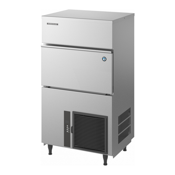
Direktlink Hoshizaki Zylindereisbereiter IM130ME-C zu Kälte-Berlin
HOSHIZAKI
IM-21 IM-100
IM-25 IM-130
IM-30 IM-160
IM-45 IM-240
IM-65
SERVICE MANUAL
NO.
E1AP-433
ISSUED:
APR. 30, 1997
REVISED: JUL. 29, 2005
Advertisement
Table of Contents

Related Manuals for Hoshizaki IM-21


Summary of Contents for Hoshizaki IM-21
- Page 1 Kälte-Berlin Direktlink Hoshizaki Zylindereisbereiter IM130ME-C zu Kälte-Berlin Inh.: Christian Berg Am Pfarracker 41 12209 Berlin Fon: +49 (0) 30 / 74 10 40 22 Fax: +49 (0) 30 / 74 10 40 21 E1AP-433 eMail: info@kaelte-berlin.de ISSUED: APR. 30, 1997 Internet: http://www.kaelte-berlin.com...
-
Page 2: Table Of Contents
CONTENTS PAGE I. SPECIFICATIONS ------------------------------------------------------------------------------------- 1 1. DIMENSIONS/CONNECTIONS----------------------------------------------------------------- 1 [a] IM-25LE (Air-cooled) -------------------------------------------------------------------------- 1 [b] IM-25CLE (Air-cooled) ----------------------------------------------------------------------- 2 [c] IM-21CLE, IM-25CLE, IM-30CLE (Air-cooled) ------------------------------------------ 3 [d] IM-45LE (Air-cooled) -------------------------------------------------------------------------- 4 [e] IM-45CLE-25 (Air-cooled) ------------------------------------------------------------------- 5 [f] IM-65LE (Air-cooled) -------------------------------------------------------------------------- 6 [g] IM-100LE, IM-130LE, IM-130ME (Air-cooled) ------------------------------------------- 7 [h] IM-100CLE (Air-cooled) ---------------------------------------------------------------------- 8 [i] IM-160ME (Air-cooled) ----------------------------------------------------------------------- 9... - Page 3 IV. OPERATING INSTRUCTIONS ------------------------------------------------------------------- 47 1. START UP ------------------------------------------------------------------------------------------ 47 2. PREPARING THE ICEMAKER FOR LONG STORAGE --------------------------------- 48 [a] IM-21, IM-25, IM-30, IM-45, IM-65 --------------------------------------------------------- 48 [b] IM-100, IM-130, IM-160, IM-240 ----------------------------------------------------------- 49 3. BIN CONTROL------------------------------------------------------------------------------------- 50 [a] BIN CONTROL SWITCH ASSEMBLY ---------------------------------------------------- 50...
- Page 4 14. CONTROLLER BOARD ---------------------------------------------------------------------- 118 [a] MODIFICATION ----------------------------------------------------------------------------- 118 [b] REPLACEMENT --------------------------------------------------------------------------- 118 15. THERMISTOR FOR CUBE CONTROL ---------------------------------------------------- 120 16. SURGE ABSORBER -------------------------------------------------------------------------- 121 17. FAN MOTOR - AIR-COOLED MODEL ONLY --------------------------------------------- 122 [a] EXCEPT IM-21/25/30CLE --------------------------------------------------------------- 122 [b] IM-21/25/30CLE ONLY -------------------------------------------------------------------- 122...
-
Page 5: Specifications
I. SPECIFICATIONS 1. DIMENSIONS/CONNECTIONS [a] IM-25LE (Air-cooled) -
Page 6: [B] Im-25Cle (Air-Cooled)
[b] IM-25CLE* (Air-cooled) *Until March 2000 production (Auxiliary Code: K-1) -
Page 7: [C] Im-21Cle, Im-25Cle, Im-30Cle (Air-Cooled)
[c] IM-21CLE, IM-25CLE*, IM-30CLE (Air-cooled) *From April 2000 production (Auxiliary Code: K-2) -
Page 8: [D] Im-45Le (Air-Cooled)
[d] IM-45LE (Air-cooled) -
Page 9: [E] Im-45Cle-25 (Air-Cooled)
[e] IM-45CLE-25 (Air-cooled) -
Page 10: [F] Im-65Le (Air-Cooled)
[f] IM-65LE (Air-cooled) -
Page 11: [G] Im-100Le, Im-130Le, Im-130Me (Air-Cooled)
[g] IM-100LE, IM-130LE, IM-130ME (Air-cooled) -
Page 12: [H] Im-100Cle (Air-Cooled)
[h] IM-100CLE (Air-cooled) -
Page 13: [I] Im-160Me (Air-Cooled)
[i] IM-160ME (Air-cooled) -
Page 14: [J] Im-240Me (Air-Cooled)
[j] IM-240ME (Air-cooled) -
Page 15: [K] Im-240M2E (Air-Cooled)
[k] IM-240M2E (Air-cooled) -
Page 16: [L] Im-25Wle, Im-30Wle (Water-Cooled)
[l] IM-25WLE, IM-30WLE (Water-cooled) -
Page 17: [M] Im-45Wle (Water-Cooled)
[m] IM-45WLE (Water-cooled) -
Page 18: [N] Im-65Wle (Water-Cooled)
[n] IM-65WLE (Water-cooled) -
Page 19: [O] Im-100Wle, Im-130Wle, Im-130Wme (Water-Cooled)
[o] IM-100WLE, IM-130WLE, IM-130WME (Water-cooled) -
Page 20: [P] Im-240Wme (Water-Cooled)
[p] IM-240WME (Water-cooled) -
Page 21: [Q] Im-240Wm2E (Water-Cooled)
[q] IM-240WM2E (Water-cooled) -
Page 22: General Information
II. GENERAL INFORMATION 1. CONSTRUCTION [a] IM-25LE, IM-45LE, IM-65LE, IM-100LE, IM-130LE, IM-130ME, IM-160ME Top Panel Front Panel (Upper) Storage Bin Bin Door Condensing Unit Front Panel (Lower) Power Cord Water Tank Water Plate Evaporator Water Valve Actuator Toggle Switch Pump Motor Bin Control Switch Air-cooled Condenser Control Box... -
Page 23: [B] Im-21Cle, Im-25Cle, Im-30Cle
[b] IM-21CLE, IM-25CLE, IM-30CLE Control Box Top Panel Front Panel (Upper) Storage Bin Bin Door Condensing Unit Front Panel (Lower) Water Tank Water Plate Evaporator Water Valve Actuator Toggle Switch Pump Motor Bin Control Switch Compressor Fan Motor Air-cooled Condenser Air Filter... -
Page 24: [C] Im-45Cle-25
[c] IM-45CLE-25 Top Panel Storage Bin Bin Door Condensing Unit Front Panel Power Cord Water Valve Water Plate Actuator Toggle Switch Evaporator Bin Control Switch Water Tank Pump Motor Actuator Motor Compressor Control Box Air Filter Air-cooled Condenser... -
Page 25: [D] Im-100Cle
[d] IM-100CLE Top Panel Air Filter Front Panel (A) Storage Bin Handle Power Cord Front Panel (B) Bin Door Front Panel (C) Louver Adjustable Leg Water Valve Water Plate Actuator Toggle Switch Pump Motor Actuator Motor Evaporator Water Tank Bin Control Switch Control Box Air-cooled Condenser Air Filter... -
Page 26: [E] Im-240Me, Im-240M2E
[e] IM-240ME, IM-240M2E Top Panel Front Panel (Upper) Storage Bin Bin Door Condensing Unit Front Panel (Lower) Power Cord Water Tank Water Plate Evaporator Water Valve Actuator Toggle Switch Pump Motor Bin Control Switch Air Filter Compressor Air-cooled Condenser Control Box... -
Page 27: [F] Im-25Wle, Im-30Wle, Im-45Wle, Im-65Wle
[f] IM-25WLE, IM-30WLE, IM-45WLE, IM-65WLE Top Panel Front Panel (Upper) Storage Bin Bin Door Condensing Unit Front Panel (Lower) Power Cord Water Tank Water Plate Evaporator Water Valve Actuator Toggle Switch Pump Motor Bin Control Switch Fan Motor Control Box Transformer Condenser... -
Page 28: [G] Im-100Wle, Im-130Wle, Im-130Wme, Im-240Wme, Im-240Wm2E
[g] IM-100WLE, IM-130WLE, IM-130WME, IM-240WME, IM-240WM2E Top Panel Front Panel (Upper) Storage Bin Bin Door Condensing Unit Front Panel (Lower) Evaporator Water Valve Bin Control Switch Actuator Motor Pump Motor Water Plate Water Tank Condenser Control Box Compressor Hot Gas Valve Transformer... -
Page 29: Controller Board
2. CONTROLLER BOARD Note: Refer to the “Hoshizaki IM Cuber Controller Board Service Manual” (E1AX-676) for the new Controller Board used for the later models (from Auxiliary Code “E-1”). IMPORTANT If receiving a service call, ask the user to turn off the power to the icemaker and turn it on again, while watching the icemaker. -
Page 30: [A] Controller Board Layout
[a] CONTROLLER BOARD LAYOUT Thermistor (Cube Control) Backup Timer VR3 Connector K4 Cube Control VR5 Defrost Control VR2 Thermistor (Calibration) *Not fitted on water- cooled models Reset Switch Water Supply Time Setting Jumper Wires Signal Ground Connector K2 Connector K1 ID Number Connector K3 Model... - Page 31 See the diagram on the right for layout of the Controller Board. Variable Resistor No. 2 through No. 5 adjustable Connector Integrated Circuit Chip LED: Light Emitting Diode Indicator Lamp Transformer Relay RESET: Reset Button To check the operation of the board, push the Reset Button only during the freeze cycle.
-
Page 32: [B] Before Checking Controller Board
[b] BEFORE CHECKING CONTROLLER BOARD Check the power source voltage and the components as shown in the table below. Component Procedure Normal 1. Actuator Toggle Manually set the switch in the FREEZE DEFROST Switch and DEFROST positions, and check the COM-NO Open continuity. -
Page 33: [C] Sequence - Led Indicators On/Off Pattern
[c] SEQUENCE - LED INDICATORS ON/OFF PATTERN... -
Page 34: [D] Fault Diagnosis
If on the first cycle, check out the Cam operation and/or Toggle Switch. If the machine has been in service for some time, the Controller Board may be at fault. REMEMBER: Hoshizaki controllers are very reliable. They also control every component’s operation. So if a component malfunctions, the controller will respond. - Page 35 INTERLOCK WATER TANK PATTERN POSSIBLE CAUSE REMEDY INDICATOR POSITION Clean or replace Clogged Air Filter and/or Condenser Replace Water leak from Water Freeze Cycle Solenoid Valve Leak Replace Gas leak from Hot Gas Solenoid Valve Gas Leak Replace Fan Motor stopped Check for leak Gas leak Replace Comp.
-
Page 36: [E] Controls And Adjustment
[e] CONTROLS AND ADJUSTMENT 1) Cube Control (VR5) A cube control on the Controller Board is factory adjusted to produce constant cubes all year around. When the user needs ice cubes with smaller or larger diameter holes, adjust the Variable Resistor VR5 (Cube Control) using a miniature flat blade screwdriver. - Page 37 3) Defrost Control (VR2) The defrost control regulates the time period between ice-drop and actuator motor restart. Any adjustment will not be required for normal operation. Factory LONGER setting is shown in the table below. When servicing or replacing the controller board, adjust the Variable Resistor VR2 using a miniature flat blade screwdriver.
- Page 38 b. IM-100LE/WLE, IM-130LE/WLE, IM-130ME/WME, IM-160ME, IM-240ME/WME, IM- 240M2E/WM2E Note: In some areas where excessively hard water (approx. 250 ppm or more) results in production of cloudy ice, change the water supply time setting as follows. Cut the jumper wire JE (marked by arrow) by a nipper.
-
Page 39: Fan Motor Control - 240Me Only
3. FAN MOTOR CONTROL - 240ME/M2E ONLY The Condenser Fan Motor rotates at two speeds. The Motor is operated by Relay X6 which is in turn controlled by the Bimetal Thermostat which is attached to the Control Box. When the Relay is energised (Thermostat contacts closed), the Motor operates at approximately half speed. -
Page 40: Installation Instructions
III. INSTALLATION INSTRUCTIONS WARNING The installation must be carried out by qualified personnel, in accordance with current regulations, according to the manufacturer’s instructions. 1. UNPACKING WARNING Children should not be allowed in reach of the packaging elements (plastic bags and expanded polystyrene) as they are potential sources of danger. CAUTION Remove shipping carton, tape(s) and packing. -
Page 41: Location
Outlet Hose 3/4-3/4 Nipple Elbow b) Scoop c) Adjustable Leg* (Except IM-21, 100CLE) * Provided for Europe/General(G50)/RINNAI only Adjustable Leg (IM-100CLE) 5) Remove shipping tape holding the Bin Control Switch by opening the Bin Door and reaching in (see Fig. 2). -
Page 42: Installation
3. The location should provide a firm and level foundation for the equipment at normal counter top height. 4. Allow 15 cm clearance at rear, sides and top for proper air circulation and ease of maintenance and/or service should they be required. 5. - Page 43 The correct replacement for the detachable fuse cover is identifiable from the manufacturer’s reference number stamped on the plug. Supply of replacement fuse covers can be obtained from Hoshizaki Parts/Service Centres. Fuses should be rated at 10A and approved to BS 1362.
-
Page 44: Water Supply And Drain Connections
5. WATER SUPPLY AND DRAIN CONNECTIONS (For the U.K. only, the connections must be in accordance with current requirements of the Model Water Byelaws 1986 SI No. 1147) * Only potable water should be used for this icemaker. * Water supply pressure should be minimum 0.5 bar and maximum 8 bar. If the pressure exceeds 8 bar, use a pressure reducing valve. - Page 45 [Air-Cooled Model Except IM-100CLE] Potable Water Inlet G3/4 Inlet Hose Drain Outlet R3/4 Water Supply Tap Inlet Hose Outlet Hose Fig. 4 Fig. 5 1) Attach the angled end of white flexible inlet hose (accessory) onto the G3/4 fitting on the rear of the icemaker as indicated (Fig.
- Page 46 Fig. 8 [WATER-COOLED MODEL] * Hoshizaki recommends that the water-cooled Condenser should be connected to a closed circuit recirculating type cooling system utilizing a tower, water chiller or similar (see Fig. 9 and 10). Water make up should be via a ball valve/break tank arrangement.
- Page 47 * Whilst connecting a water-cooled Condenser to a mains water (potable) supply will not affect the performance of the machine, it will most certainly cause a high use/waste of a valuable resource and is not recommended. * The services of a licensed or coded plumber should be used to ensure a correct installation. * The connections should be made properly in compliance with the applicable national or local regulations.
- Page 48 4) By means of a suitable spanner or wrench, tighten the 1/2-3/4 nipples (accessory) into the Rc1/2 fittings on the rear of the icemaker as indicated. P.T.F.E. tape and/or a suitable sealing compound should be used to obtain a leak free joint. Note:Jointing compounds should be approved and suitable for potable water use.
- Page 49 * When adjusting the Water Regulator to increase the pressure or to lower the temperature of the cooling water, do not exceed the following ranges to prevent erosion in the water circuit: Flow Speed: 2 m/sec or less Flow Rate: 5.9 lit/min or less * Water flow can be reduced down to 60%.
-
Page 50: Final Check List
6. FINAL CHECK LIST 1) Is the icemaker level? 2) Is the icemaker in a site where ambient temperatures are a minimum of 1°C and maximum 40°C all year around? 3) Is there at least 15 cm clearance around the icemaker for easy maintenance and service? 4) Have all shipping carton, tape(s) and packing been removed from the icemaker? 5) Have all electrical and piping connections been made? 6) Has the power supply voltage been tested or checked against the nameplate rating? -
Page 51: Operating Instructions
IV. OPERATING INSTRUCTIONS WARNING 1. This icemaker is designed to produce and store edible ice. To keep the icemaker hygienic: * Wash your hands before removing ice. Use the Plastic Scoop provided (accessory). * The Storage Bin is for ice use only. Do not store anything else in the Bin. * Clean the Storage Bin before use (see “V. -
Page 52: Preparing The Icemaker For Long Storage
Drain the icemaker to prevent damage to the water supply line at subfreezing temperatures, using air or carbon dioxide. Shut off the icemaker until proper air temperature is resumed. [a] IM-21, IM-25, IM-30, IM-45, IM-65 1) Close the water supply tap, and remove the Inlet Hose. -
Page 53: [B] Im-100, Im-130, Im-160, Im-240
[b] IM-100, IM-130, IM-160, IM-240 1) Close the water supply tap, and remove the [Normal Position] Inlet Hose. 2) Remove the Front Panels (Upper and Lower). 3) Remove the screw located on the front of the Water Tank. Bracket 4) Move the Tank Drain Pipe to the drain Tank Drain Pipe position. -
Page 54: Bin Control
Keep away from the Water Plate or Drain Pan to prevent jamming. Running Bin full Fragile (Tripped) Keep away from water plate or drain pan. Fig. 14 [a] BIN CONTROL SWITCH ASSEMBLY Bracket Microswitch Switch Bracket Cover Actuator Detector for IM-45,65 Detector (B) for IM-21,25,30,100,130,160,240 Fig. 15... -
Page 55: [B] Removal
[b] REMOVAL BRACKET COVER Push the two Pawls and remove the Bracket Cover. SWITCH Pull out the Switch, holding the Rubber Leads Cap. Handle with care. SWITCH ACTUATOR Insert a flat blade screwdriver and wrench it slightly to pull out the Switch Actuator. Handle with care to prevent damage to the cam surface of the Actuator. -
Page 56: Maintenance Instructions
1) Either mix 3 litres of water with 11 ml of 5.25% sodium hypochlorite solution in a suitable container, or the recommended Hoshizaki sanitiser as directed. 2) Soak the Scoop in the solution for more than 3 minutes. Rinse thoroughly, and shake to remove surplus liquid. - Page 57 6) Rinse thoroughly with fresh water and a clean cloth to wipe off the solution. Close the Bin Door. Note: Some solutions may cause damage to the Bin liner surfaces or corrosion on the metal parts. Always rinse the sanitiser unless directed otherwise by Hoshizaki guidelines. [4] Air Filter (Air-Cooled Model Only) A plastic mesh Air Filter is fitted to remove dirt or dust from the air, preventing the Condenser from getting clogged.
-
Page 58: Water Valve
2. WATER VALVE 1) Unplug the icemaker or disconnect the power source. 2) Close the water supply tap. 3) Remove the Top Panel and Front Panel (Upper). 4) Disconnect the Inlet Hose from the Water Valve. 5) Remove the Mesh Filter from the Water Valve. 6) Clean the Mesh using a brush. -
Page 59: Water-Cooled Condenser
3. WATER-COOLED CONDENSER Deposits inside the water circuit of the Water-cooled Condenser decrease cooling performance. Clean inside of the Condenser by circulating a cleaning solution. 1) Prepare the following: Cleaning solution [Read and follow any instructions on label or bottle.] Pump Container for solution Hose... -
Page 60: Icemaking Water System
2. Always wear rubber gloves, eye protectors, apron, etc. for safe handling of the cleaner and sanitizer. 3. Use the cleaners and sanitizers recommended by Hoshizaki. Contact your local Hoshizaki office for further details. (The instructions below give an example of those recommended cleaners and sanitizers.) 4. - Page 61 9) After the ice has dropped and the Water Pan begins to close, move the Washing Switch on the bottom [IM-21/25/30CLE only] or right side [except IM-21/25/30CLE] of the Control Box Fig. 20 to the “WASH” position. See Fig. 21.
- Page 62 IM-240 Mix 44 ml of the sodium hypochlorite solution with 11.4 litres of water. * Alternatively use the Hoshizaki recommended sanitizer as directed by the relevant instructions. 15) Repeat the above steps 5), 6) and 7), and close the water supply tap.
- Page 63 icemaker will resume icemaking process.) 22) Replace the Front Panel and Top Panel in their correct positions. 23) Complete Storage Bin cleaning as detailed in V. 1. [3]. IMPORTANT Be sure to operate the Bin Control Switch as specified in 11) and 17) within 40 minutes after the Water Pan closes.
-
Page 64: Technical Information
VI. TECHNICAL INFORMATION 1. WATER CIRCUIT AND REFRIGERANT CIRCUIT [a] IM-21CLE, IM-25LE, IM-25CLE, IM-30CLE, IM-45LE, IM-45CLE-25, IM-65LE (Air-cooled) Water Inlet Capillary Tube Accumulator Evaporator Water Pan Pump Drain Pan Motor Controller Board Hot Gas Valve Drier Condenser Compressor Water Circuit Refrigeration Circuit... -
Page 65: [B] Im-100Le, Im-100Cle, Im-130Le, Im-130Me, Im-160Me (Air-Cooled)
[b] IM-100LE, IM-100CLE, IM-130LE, IM-130ME, IM-160ME (Air-cooled) Controller Board Water Inlet Expansion Valve Bulb Evaporator Thermistor Drier Water Pan Water Pump Hot Gas Valve Compressor Condenser Water Circuit Refrigeration Circuit... -
Page 66: [C] Im-240Me (Air-Cooled)
[c] IM-240ME (Air-cooled) Water Valve Expansion Valve Evaporator Thermistor Controller Board Expansion Valve Bulb Water Pan Water Pump Drier Condenser Pressure Switch Hot Gas Fan Motor Valve Strainer Compressor Water Circuit Refrigerant Circuit... -
Page 67: [D] Im-240M2E (Air-Cooled)
[d] IM-240M2E (Air-cooled) Water Valve Expansion Valve Evaporator Thermistor Controller Board Expansion Valve Bulb Water Pan Water Pump Condenser Hot Gas Fan Motor Valve Strainer Compressor Pressure Switch Drier Water Circuit Refrigerant Circuit... -
Page 68: [E] Im-25Wle, Im-30Wle, Im-45Wle, Im-65Wle, Im-100Wle, Im-130Wle, Im-130Wme, Im-240Wme (Water-Cooled)
[e] IM-25WLE, IM-30WLE, IM-45WLE, IM-65WLE, IM-100WLE, IM-130WLE, IM-130WME, IM-240WME (Water-cooled) Controller Board Water Inlet Expansion Valve Bulb Evaporator Thermistor Water Pan Water Pump Pressure Switch Hot Gas Valve Compressor Strainer Drier Condenser Water Regulator Water Circuit Refrigeration Circuit... -
Page 69: [F] Im-240Mw2E (Water-Cooled)
[f] IM-240WM2E (Water-cooled) Controller Board Water Inlet Expansion Valve Bulb Evaporator Thermistor Water Pan Water Pump Pressure Switch Hot Gas Valve Compressor Strainer Drier Condenser Water Regulator Water Circuit Refrigeration Circuit... -
Page 70: Wiring Diagram
2. WIRING DIAGRAM [a] IM-21CLE, IM-25LE, IM-25CLE, IM-30CLE, IM-25WLE, IM-30WLE... -
Page 71: [B] Im-25L, Im-25Cl, Im-25Wl
[b] IM-25L, IM-25CL, IM-25WL... -
Page 72: [C] Im-45Le, Im-45Cle-25, Im-45Wle
[c] IM-45LE, IM-45CLE-25, IM-45WLE... -
Page 73: [D] Im-65Le, Im-65Wle
[d] IM-65LE, IM-65WLE... -
Page 74: [E] Im-65L, Im-65Wl
[e] IM-65L, IM-65WL... -
Page 75: [F] Im-100Le, Im-100Cle, Im-100Wle
[f] IM-100LE, IM-100CLE, IM-100WLE Note: The Washing Switch is provided only after the Auxiliary Code “H-0”. -
Page 76: [G] Im-130Le, Im-130Wle
[g] IM-130LE, IM-130WLE Note: The Washing Switch is provided only after the Auxiliary Code “H-0”. -
Page 77: [H] Im-130Le-21, Im-130Wle-21
[h] IM-130LE-21, IM-130WLE-21 Note: The Washing Switch is provided only after the Auxiliary Code “H-0”. -
Page 78: [I] Im-130Me, Im-130Wme
[i] IM-130ME, IM-130WME Note: The Washing Switch is provided only after the Auxiliary Code “H-0”. -
Page 79: [J] Im-130Me-21, Im-130Wme-21
[j] IM-130ME-21, IM-130WME-21 Note: The Washing Switch is provided only after the Auxiliary Code “H-0”. -
Page 80: [K] Im-160Me
[k] IM-160ME... -
Page 81: [L] Im-240Me, Im-240Wme
[l] IM-240ME, IM-240WME... -
Page 82: [M] Im-240M2E, Im-240Mw2E
[m] IM-240M2E, IM-240WM2E... -
Page 83: Performance Data
3. PERFORMANCE DATA (Ice Production = Capacity when shipped from factory) (*Values for icemaking water only. Use a cooling tower for cooling water.) Ambient Temp. (°C) Model Water Temp. (°C) IM-21CLE Ice Production (kg/d) Freeze Cycle Time (min) 15.6 27.5 34.5 (50Hz) Defrost Cycle Time (min) - Page 84 (Ice Production = Capacity when shipped from factory) (*Values for icemaking water only. Use a cooling tower for cooling water.) Ambient Temp. (°C) Model Water Temp. (°C) IM-25WLE-25 Ice Production (kg/d) Freeze Cycle Time (min) 10.5 13.2 14.5 (50Hz) Defrost Cycle Time (min) Water Consumption (lit/h)* Electric Consumption (W) Head Pressure [median] (bar)
- Page 85 (Ice Production = Capacity when shipped from factory) (*Values for icemaking water only. Use a cooling tower for cooling water.) Ambient Temp. (°C) Model Water Temp. (°C) IM-45LE Ice Production (kg/d) Freeze Cycle Time (min) 15.6 (50Hz) Defrost Cycle Time (min) Water Consumption (lit/h) 11.2 10.8...
- Page 86 (Ice Production = Capacity when shipped from factory) (*Values for icemaking water only. Use a cooling tower for cooling water.) Ambient Temp. (°C) Model Water Temp. (°C) IM-65LE Ice Production (kg/d) 38.5 Freeze Cycle Time (min) 28.5 32.5 (60Hz) Defrost Cycle Time (min) Water Consumption (lit/h) 10.2 Electric Consumption (W)
- Page 87 (Ice Production = Capacity when shipped from factory) (*Values for icemaking water only. Use a cooling tower for cooling water.) Ambient Temp. (°C) Model Water Temp. (°C) IM-100LE Ice Production (kg/d) Freeze Cycle Time (min) (50Hz) Defrost Cycle Time (min) Water Consumption (lit/h) 31.5 17.4...
- Page 88 (Ice Production = Capacity when shipped from factory) (*Values for icemaking water only. Use a cooling tower for cooling water.) Ambient Temp. (°C) Model Water Temp. (°C) IM-100WLE-23 Ice Production (kg/d) Freeze Cycle Time (min) 22.5 (60Hz) Defrost Cycle Time (min) Water Consumption (lit/h)* 21.6 16.2...
- Page 89 (Ice Production = Capacity when shipped from factory) (*Values for icemaking water only. Use a cooling tower for cooling water.) Ambient Temp. (°C) Model Water Temp. (°C) IM-130WLE-21 Ice Production (kg/d) Freeze Cycle Time (min) 10.5 10.5 (50Hz) Defrost Cycle Time (min) Water Consumption (lit/h)* 34.2 26.5...
- Page 90 (Ice Production = Capacity when shipped from factory) (*Values for icemaking water only. Use a cooling tower for cooling water.) Ambient Temp. (°C) Model Water Temp. (°C) IM-240ME Ice Production (kg/d) Freeze Cycle Time (min) 15.8 24.3 (60Hz) Defrost Cycle Time (min) Water Consumption (lit/h) 31.3 20.9...
- Page 91 (Ice Production = Capacity when shipped from factory) (*Values for icemaking water only. Use a cooling tower for cooling water.) Ambient Temp. (°C) Model Water Temp. (°C) IM-240M2E-21 Ice Production (kg/d) Freeze Cycle Time (min) 11.1 13.2 (50Hz) Defrost Cycle Time (min) Water Consumption (lit/h)* 25.5 12.5...
- Page 92 (Ice Production = Capacity when shipped from factory) (*Values for icemaking water only. Use a cooling tower for cooling water.) Ambient Temp. (°C) Model Water Temp. (°C) IM-240WM2E-23 Ice Production (kg/d) Freeze Cycle Time (min) 13.2 15.2 16.7 (50Hz) Defrost Cycle Time (min) Water Consumption (lit/h)* 30.4 24.6...
- Page 93 Suction Pressure and Evaporator Temp. (Air-cooled Models) 50Hz Ambient Temp. (°C) MODEL Water Temp. (°C) Suction Pressure IM-25LE Peak (bar) IM-25CLE Evaporator Inlet Temp. (°C) Suction Pressure IM-45LE Peak (bar) IM-45CLE Evaporator Inlet Temp. (°C) Suction Pressure Peak (bar) IM-65LE Evaporator Inlet Temp.
- Page 94 Suction Pressure and Evaporator Temp. (Water-cooled Models) 50Hz Ambient Temp. (°C) MODEL Water Temp. (°C) Suction Pressure Peak (bar) IM-25WLE Evaporator Inlet Temp. (°C) Suction Pressure Peak (bar) IM-45WLE Evaporator Inlet Temp. (°C) Suction Pressure Peak (bar) IM-65WLE Evaporator Inlet Temp.
-
Page 95: Service Diagnosis
VII. SERVICE DIAGNOSIS 1. NO ICE PRODUCTION PROBLEM CHECK POSSIBLE CAUSE REMEDY [1] The icemaker a) Power Source 1. OFF position. 1. Move to ON position. will not start. 2. Loose connections. 2. Tighten. 3. Bad contacts. 3. Check for continuity and replace. - Page 96 PROBLEM CHECK POSSIBLE CAUSE REMEDY [2] (Continued) 3. Condenser water 3. Check for recommended pressure too low or OFF pressure. (water-cooled). b) Water Regulator 1. Set too high. 1. Adjust lower. (water-cooled) 2. Clogged or defective. 2. Clean or replace. c) Overload 1.
- Page 97 PROBLEM CHECK POSSIBLE CAUSE REMEDY [6] (Continued) 3. Wiring to Pump Motor. 3. Check for loose connection or open, and replace. 4. Defective or bound 4. Replace and clean. impeller. 5. Mechanical Seal worn 5. Check and replace. out. e) Controller Board 1. Defective. 1.
-
Page 98: Low Ice Production
2. LOW ICE PRODUCTION PROBLEM CHECK POSSIBLE CAUSE REMEDY [1] Freeze cycle a) Water Supply 1. Low pressure. 1. Check for recommended time is too pressure. long. b) Water 1. Too high. 1. Check for recommended Temperature water temperature. c) Water Quality 1. -
Page 99: Abnormal Ice
3. ABNORMAL ICE PROBLEM CHECK POSSIBLE CAUSE REMEDY [1] Large-hole a) Water Supply 1. Low pressure. 1. Check for recommended cubes. Line pressure. b) Ambient or 1. Too high. 1. Check for recommended Water temperatures. Temperature c) Air Filter, 1. Clogged. 1. -
Page 100: Others
4. OTHERS PROBLEM CHECK POSSIBLE CAUSE REMEDY [1] Icemaker will a) Bin Control 1. Out of position. 1. Place in position. not stop when Switch 2. Bad contacts. 2. Check for continuity and Bin is filled with replace. ice. b) Controller Board 1. See “II. 2. CONTROLLER BOARD”. [2] Abnormal a) Pump Motor 1. -
Page 101: Adjustment
VIII. ADJUSTMENT 1. EXPANSION VALVE The Expansion Valve is factory-adjusted. Do not adjust it except at replacement or service. Adjust the valve setting, if necessary, as follows: 1) Remove the Cap Nut. 2) Rotate the Adjust Screw. 3) Watch holes of ice cubes produced. Standard setting is that Evaporator inlet side and outlet side cubes have almost the same diameters. -
Page 102: Water Regulating Valve - Water-Cooled Model Only
2. WATER REGULATING VALVE - WATER-COOLED MODEL ONLY The Water Regulating Valve is factory-adjusted. Do not adjust it except at replacement or service. Adjust the valve setting, if necessary, as follows: 1) Attach a pressure gauge to high-side line, or prepare a thermometer to check Condenser drain temperature. -
Page 103: Removal And Replacement
IX. REMOVAL AND REPLACEMENT 1. SERVICE FOR REFRIGERANT LINES [a] SERVICE INFORMATION 1) Allowable Compressor Opening Time and Prevention of Lubricant Mixture [R134a/ R404A] The compressor must not be opened more than 30 minutes in replacement or service. Do not mix lubricants of different compressors even if both are charged with the same refrigerant, except when they use the same lubricant. -
Page 104: [B] Refrigerant Recovery
7) Evacuation, Vacuum Pump and Refrigerant Charge [R134a/R404A] Never allow the oil in the vacuum pump to flow backward. The vacuum level and vacuum pump may be the same as those for the current refrigerants. However, the rubber hose and gauge manifold to be used for evacuation and refrigerant charge should be exclusively for R134a/R404A. -
Page 105: [C] Evacuation And Recharge
[c] EVACUATION AND RECHARGE 1) Attach Charging Hoses, a Service Manifold and a Vacuum Pump to the system. If possible, use Quick Release Connectors onto the Access Valves (especially on the high side). 2) Turn on the Vacuum Pump. 3) Allow the Vacuum Pump to pull down to a 760 mmHg vacuum. Evacuating period depends on the pump capacity. -
Page 106: Compressor
17) Replace the Louver or Front Panel and Rear Mesh in their correct positions. 18) Plug in the icemaker or connect the power source. Note: Hoshizaki recommends that Compressor starting electrics are always replaced at the same time as the Compressor. -
Page 107: Drier
3. DRIER 1) Unplug the icemaker or disconnect the power source. 2) Remove the Rear Mesh. 3) Recover the refrigerant and store it in a proper container, if required by an applicable law (See “1. [b] REFRIGERANT RECOVERY”). 4) Remove the Drier Holder, if any, and pull the Drier toward you for easy service. 5) Remove the Drier using brazing equipment. -
Page 108: Expansion Valve
4. EXPANSION VALVE IMPORTANT Always install a new Drier every time the sealed refrigeration system is opened. Do not replace the Drier until after all other repair or replacement has been made. 1) Unplug the icemaker or disconnect the power source. 2) Remove the Top, Front (Upper) and Rear Mesh Panels. -
Page 109: Evaporator
5. EVAPORATOR IMPORTANT Always install a new Drier every time the sealed refrigeration system is opened. Do not replace the Drier until after all other repair or replacement has been made. 1) Unplug the icemaker or disconnect the power source. 2) Remove the Top, Front (Upper) and Rear Mesh Panels. -
Page 110: Hot Gas Valve
6. HOT GAS VALVE IMPORTANT Always install a new Drier every time the sealed refrigeration system is opened. Do not replace the Drier until after all other repair or replacement has been made. 1) Unplug the icemaker or disconnect the power source. 2) Remove the Louver (Right Side) and Rear Mesh Panel. -
Page 111: Water Regulating Valve - Water-Cooled Model Only
7. WATER REGULATING VALVE - WATER-COOLED MODEL ONLY [a] VALVE BODY 1) Unplug the icemaker or disconnect the power source. 2) Close the water supply tap. 3) Remove the Front Panel (Lower) and Louver (Left Side). 4) Disconnect the flare connections of the Water Regulating Valve. 5) Remove the valve from the Bracket. - Page 112 6) Cut off the Capillary Tubes of the Valve and High-pressure Switch, using a file and pliers. Be careful not to damage the Capillary Tube end. 7) Disconnect the flare connections from the Bracket. 8) Remove the screws and the valve from the Bracket. 9) Install the new valve, and insert the Capillary Tubes into the Copper Tube.
-
Page 113: Water Pan Assembly
8. WATER PAN ASSEMBLY 1) Remove the Top Panel and Front Panel (Upper). 2) Remove the Front Panel (Lower) [except IM-21/25/30CLE], and push the Reset Switch on the Control Box to open the Water Pan. 3) Unplug the icemaker or disconnect the power source. - Page 114 INDEX NO. DESCRIPTION Water Plate Water Tank Water Plate Bracket Drain Guide Pump Motor Bracket Friction Plate Spring Hook Screw Pump Tubing (Suction) Pump Tubing (Discharge) Clamp - nylon tie Water Pump Assembly U-Packing Fig. 28...
-
Page 115: Pump Motor
9. PUMP MOTOR 1) Unplug the icemaker or disconnect the power source. 2) Remove the Top Panel and Front Panel (Upper). 3) Disconnect the Pump Motor leads in the Wiring Channel. 4) Remove screws and the Pump Motor from the Bracket. 5) Disconnect the Pump Suction and Discharge Tubings. -
Page 116: Water Valve
10. WATER VALVE 1) Close the water supply tap. 2) Unplug the icemaker or disconnect the power source. 3) Remove the Top Panel. 4) Disconnect the Receptacle (leads) from the Water Valve. 5) Remove the Valve Outlet tubing by releasing the Clamp. 6) Remove the Inlet Hose and Water Valve. -
Page 117: Actuator Motor
11. ACTUATOR MOTOR 1) Remove the Top Panel and Front Panel (Upper). 2) Remove the Front Panel (Lower) [except IM-21/25/30CLE], and push the Reset Switch on the Control Box to open the Water Pan. 3) Unplug the icemaker or disconnect the power source. -
Page 118: Cam Arm
[b] CAM ARM (B) - REAR SIDE 1) Remove the Top Panel and Front Panel (Upper). 2) Remove the Front Panel (Lower) [except IM-21/25/30CLE], and push the Reset Switch on the Control Box to open the Water Pan. 3) Unplug the icemaker or disconnect the power source. -
Page 119: Actuator Toggle Switch
13. ACTUATOR TOGGLE SWITCH 1) Unplug the icemaker or disconnect the power source. 2) Remove the Top Panel and Front Panel (Upper). 3) Remove the Hex Nut holding the Actuator Toggle Switch. 4) Cut off the Nylon Tie holding the Vinyl Cover Bag. 5) Disconnect the Receptacle of the leads. - Page 120 Fig. 30...
- Page 121 ICEMAKING ASSEMBLY AND CAM MECHANISM INDEX NO. DESCRIPTION Water Pan Assembly Bin Control Switch Assembly Actuator Motor Actuator Motor Bracket Cam Arm (A) Cam Arm (B) Cam Shaft Extension Spring Actuator Toggle Switch Switch Washer Switch Cover Cam Shaft Bearing Bearing (A) Bearing (B) Collar - Spacer...
-
Page 122: Controller Board
[b] REPLACEMENT 1) Unplug the icemaker or disconnect the power source. 2) Remove the Front Panel (Lower) [except IM-21/25/30CLE]. 3) Remove screws and the Control Box Cover. 4) Pull the Shield Plate slightly toward you, and disconnect the Signal Ground wire. - Page 123 [IM-21/25/30CLE only] Shield Plate Control Box Cover Control Box Controller Board Signal Ground Wire Bushing Nylon Tie (Do not cut off) [Except IM-21/25/30CLE] Pawl Nylon Tie (Do not cut off) Control Box Cover Bushing Fuse Holder Base Signal Ground Wire...
-
Page 124: Thermistor For Cube Control
15. THERMISTOR FOR CUBE CONTROL 1) Unplug the icemaker or disconnect the power source. 2) Remove the Top Panel, Front Panel and Pipe Cover (Rear). 3) Remove the Connector K4 on the Controller Board, referring to “14. [b] REPLACEMENT.” 4) Unscrew and remove the Thermistor Holder and Thermistor, located on the Evaporator (Front Side). -
Page 125: Surge Absorber
16. SURGE ABSORBER 1) Turn off the Control Switch or disconnect the power source. 2) Remove the Front Cover [except IM-21/25/30CLE]. 3) Remove two screws at the front bottom of the Control Box, and remove the Control Box Cover. 4) Remove the Quick Disconnect Terminal from the Surge Absorber. -
Page 126: Fan Motor - Air-Cooled Model Only
17. FAN MOTOR - AIR-COOLED MODEL ONLY [a] EXCEPT IM-21/25/30CLE 1) Unplug the icemaker or disconnect the power source. 2) Remove the Front Panel (Lower) and Louver (Right Side). 3) Remove the Control Box. 4) Disconnect the Connector of the Fan Motor. - Page 127 CAUTION Keep the leads away from any moving parts (ex. fan), hot parts and sharp edges. 10) Replace the Fan Motor Guard and Front Panel (Lower) in their correct positions, and fix them with the machine screws. 11) Push the icemaker back in position, if it has been pulled out for service. Plug in the icemaker or connect the power source.
- Page 128 Note: 1. While removing and fitting the securing bolt of the Fan Motor Bracket (Rear), hold the icemaker in position using a spacer at the bottom to prevent overturn. 2. Tighten the securing bolts with a spanner or the like. 3.
- Page 129 HOSHIZAKI EUROPE LTD. UNIT A, STAFFORD PARK 18, TELFORD, SHROPSHIRE TF3 3DJ ENGLAND PHONE: 01952-291777...
Need help?
Do you have a question about the IM-21 and is the answer not in the manual?
Questions and answers