Table of Contents
Advertisement
Quick Links
Advertisement
Table of Contents

Related Manuals for Inovance CS500


Summary of Contents for Inovance CS500
- Page 1 efesotomasyon.com...
-
Page 2: Table Of Contents
1.2.14 Adaptable Motor..................11 Chapter 2 Product Information ..................12 2.1 Designation Rules....................12 2.2 Nameplate ........................ 12 2.3 CS500 Models and Technical Data................. 12 2.4 Technical Specifications..................13 2.5 Physical Dimensions and Mounting Dimensions ......... 15 2.5.1 Physical Dimensions................15 2.5.2 Physical Dimensions and Mounting Dimensions ........ - Page 3 4.4 Starting or Stopping the AC Drive ..............36 4.4.1 Selecting the Source of the Start/Stop Command ........36 Function Code......................36 Parameter Name..................... 36 Setting Range......................36 Description ......................36 Press RUN or STOP to start or stop the AC drive..........36 The DI terminal needs to be defined as the run/stop terminal......
- Page 4 Appendix C Relay Extension Card Especially for the Crane AC Drive (CS70RC1) ..........................98 C.1 Overview ....................98 C.2 Mechanical Installation and Functions of Control Terminals ....... 98 C.3 Parameter Setting ..................99 efesotomasyon.com...
-
Page 5: Preface
The CS500 is mainly used to drive the asynchronous motor for the control of upward, downward and horizontal movement, slewing, and walking of the crane equipment. - Page 6 Connection to Peripheral Devices Do not install the capacitor or surge suppressor on the output side of the AC drive. Otherwise, it may cause faults to the AC drive or damage to the capacitor and surge suppressor. Inputs/Outputs (main circuit) of the AC drive contain harmonics, which may interfere with the communication device connected to the AC drive.
-
Page 7: Chapter 1 Safety Information And Precautions
Read this chapter carefully so that you have a thorough understanding. Installation, commissioning or maintenance must be performed in conjunction with this chapter. Inovance will assume no liability or responsibility for any injury or loss caused by improper operation. 1.1 Safety Information 1.1.1 Before Installation... - Page 8 1.1.3 At Wiring Wiring must be performed only by qualified personnel under instructions described in this manual. Otherwise, unexpected accident may result. A circuit breaker must be used to isolate the power supply and the AC drive. Otherwise, a fire may result.
-
Page 9: Precautions
The AC drive automatically performs safety check on the external strong-current circuit after power-on. Do not touch the U, V, W terminals and wiring terminals of the motor. Otherwise, electric shock may result. Prevent personal injury during motor rotation if motor auto-tuning is required. Do not change the factory parameters of the AC drive. -
Page 10: Running At Over 50 Hz
1.2.11 Altitude and De-rating In places where the altitude is above 1000 m and the cooling effect becomes worse due to rare air, it is necessary to de-rate the AC drive. Contact the agent or Inovance for technical support. 1.2.12 Special Usage If wiring that is not described in this manual such as common DC bus is applied, contact the agent or Inovance for technical support. -
Page 11: Adaptable Motor
AC drive based on the motor nameplate. If you want to use the AC drive to drive a permanent magnet synchronous motor (PMSM), consult Inovance. The cooling fan and rotor shaft of a non-variable-frequency motor are coaxial, and the cooling effect of the fan degrades when the rotating speed reduces. -
Page 12: Chapter 2 Product Information
Chapter 2 Product Information 2.1 Designation Rules Figure 2-1 Designation rules of the CS500 CS500 - 4T 5.5 G B Blank None Including braking unit 380 V Three-phase General Mapping relationship Motor power (kW) 2.2 Nameplate Figure 2-2 Nameplate of the CS500 2.3 CS500 Models and Technical Data... -
Page 13: Technical Specifications
CS500-4T355G 500.0 665.0 650.0 CS500-4T400G 565.0 785.0 725.0 If you need AC drives of other voltage classes, contact the agent or Inovance. 2.4 Technical Specifications Table 2-2 Technical specifications of the CS500 Item Specifications Basic Maximum frequency 150 Hz features 0.5–16 kHz, adjusted automatically based on the load... - Page 14 Item Specifications Closed-loop vector control (CLVC) Voltage/Frequency (V/F) control 0.5 Hz: 150% (SFVC) Startup torque 0 Hz: 180% (CLVC) Speed range 1:100 (SFVC) 1:1000 (CLVC) Speed stability ±0.5% (SFVC) ±0.02% (CLVC) Torque control accuracy ±5% (CLVC) 60s for 150% of the rated current, 10s for 180% of the rated Overload capability current, 3s for 200% of the rated current Automatic torque boost...
-
Page 15: Physical Dimensions And Mounting Dimensions
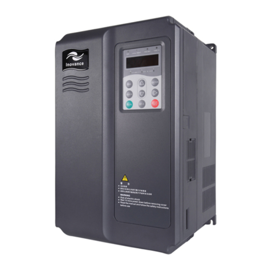
9.8 m/s for below 20 Hz, and 5.9m/s for above 20 Hz Storage temperature –20 C to +70 C 2.5 Physical Dimensions and Mounting Dimensions 2.5.1 Physical Dimensions Figure 2- 3 CS500 physical appearance Operation Front cover panel Middle cover Bottom... -
Page 16: Physical Dimensions And Mounting Dimensions
Figure 2-5 Physical dimensions & mounting dimensions of 18.5 kW to 400 kW 2.5.2 Physical Dimensions and Mounting Dimensions Table 2-3 Physical dimensions and mounting dimensions of the CS500 Mounting Mounting Hole Physical Size Hole Weight (mm) (mm) CS500 Model... -
Page 17: Physical Dimensions And Mounting Dimensions Of The External Operation Panel
1060 Ø12 CS500-4T220G CS500-4T250G CS500-4T280G CS500-4T315G CS500-4T355G 1300 1203 1358 Ø16 CS500-4T400G 2.5.3 Physical Dimensions and Mounting Dimensions of the External Operation Panel Figure 2-6 Physical dimensions of the CS500 76.00 27.00 15.00 Crystal joint 10.00 Unit: mm 3.50/typ2 efesotomasyon.com... -
Page 18: Mounting Dimensions Of The External Dc Reactor
160 190 125 161 192 255 195 10*15 Ø12 DCL-0200 CS500-4T110G 160 190 125 161 192 255 195 10*15 Ø12 DCL-0250 CS500-4T132G/160G/185G 160 190 125 161 192 255 195 10*15 Ø12 DCL-0360 CS500-4T200G/220G 190 230 93 128 250 325 200 13*18 Ø15 DCL-0600... -
Page 19: Optional Parts
Installation of External DC Reactor The CS500 AC drives of 75 kW and above are configured with an external DC reactor as standard. The DC reactor is packed in separate wooden box for delivery. When installing the DC reactor, remove the shorting copper busbar between the main circuit connection terminals P and +. -
Page 20: Periodic Inspection
Measure the static capacitance. jumping Measure the insulating resistance. Electrolytic aging 2.7.4 Storage of the AC Drive For storage of the AC drive, pay attention to the following two aspects: Pack the AC drive with the original packing box provided by Inovance. efesotomasyon.com... -
Page 21: Warranty Agreement
CS500 model based on the adaptable motor specified in this manual, and compare the rated current of the motor and that of the CS500. The overload capacity of the CS500 takes effect to the startup and braking process only when the model is proper. Any short-time overload during running changes the load speed. -
Page 22: Chapter 3 Mechanical And Electrical Installation
Less than 0.6 g, far away from the punching machine 3.1.2 Requirements for Installation Space The clearance that needs to be reserved varies with the power class of the CS500, as shown in the following figure. Figure 3-1 Clearance around the CS500 for installation If multiple AC drives are connected together, install them side by side. -
Page 23: Removal And Installation Of The
CS500-4T15GB plastic housing, CS500-4T18.5GB and above use the sheet metal housing. The following figures show the procedure of removing the plastic housing and the sheet metal housing. Figure 3-3 Operation of removing the plastic housing Use the tool to press inward so that the hooks of the front cover get out from the hook slot. -
Page 24: Usage Description Of Peripheral Electrical Devices
Cable of Cable of Cable of Input MCCB Contactor Output Side Control CS500 Model Side Main Circuit Main Circuit Circuit CS500-4T3.7GB CS500-4T5.5GB CS500-4T7.5GB CS500-4T11GB CS500-4T15GB CS500-4T18.5GB CS500-4T22GB CS500-4T30GB CS500-4T37G CS500-4T45G CS500-4T55G CS500-4T75G CS500-4T90G CS500-4T110G CS500-4T132G CS500-4T160G CS500-4T185G 150 x 2... -
Page 25: Wiring
If the distance between the AC drive and the motor is greater than 50 m, install the AC output reactor. 3.2.3 Wiring The following figures show the three-phase wiring of the CS500. Figure 3-5 Three-phase wiring for the CS500 of 30 kW or below efesotomasyon.com... - Page 26 Figure 3-6 Three-phase wiring for the CS500 of 37 kW to 55 kW Figure 3-7 Three-phase wiring for the CS500 of 75 kW or above Braking resistor External reactor Braking unit MCCB Three-phase – 380 V Input power 50/60 Hz...
-
Page 27: Main Circuit Terminals And Wiring
Do not connect the braking resistor directly to the (+), (-) terminals of the DC bus. Otherwise, a fire may result. Terminal Arrangement Maximum Wiring Torque of the CS500 Size of the Power Torque Driver Terminal CS500 kgf.cm T0.7GB... - Page 28 Maximum Wiring Size of Torque of the CS500 the Power Terminal Torque Driver CS500 kgf.cm T7.5GB 4.0 12 28±0.5 T11GB 4.0 12 28±0.5 T15GB 6.0 10 28±0.5 Function Description The following table describes the power terminals of the AC drive main circuit.
-
Page 29: Control Circuit Terminals And Wiring
the AC drive and even cause fire. 3. Terminals (+), PB for connecting the braking resistor: The connecting terminals of the braking resistor are effective only for the AC drive of 30 kW or below with a built-in braking unit. The cable length of the braking resistor must be less than 5 m. - Page 30 Terminal Type Terminal Name Function Description Symbol 1. Input range: 0–10 VDC/4–20 mA, decided by jumper J3 on the control board AI2-GND 2. Input impedance: 100 k (voltage input), 500 (current input) DI1-COM 1. Optical coupling isolation, compatible with dual DI2-COM polarity input 2.
- Page 31 Figure 3-9 Wiring of AI terminals in special scenarios Cross or wind two to three coils in the same direction CS500 0.022 uF, 50 V Ferrite magnetic core 2. Wiring of DI terminals Generally, shielded cable must be used and the cable length must be less than 20 m.
- Page 32 2) Wiring of dry contact common anode Figure 3-11 Wiring of dry contact common anode +24V +24V 3.3K 3.3K Control board of the AC drive In such wiring mode, remove the jumper bar between +24V and OP. Connect OP to CME. If external power supply is used, remove the jumper bar between CME and COM.
- Page 33 Do not reverse the polarity of the absorption diode during installation, as shown in the following figure. Otherwise, the 24 VDC power supply is damaged immediately if there is digital output. Figure 3-14 Poliarity installation of the absorption diode +24V CS500 efesotomasyon.com...
-
Page 34: Chapter 4 Operation And Display
Chapter 4 Operation and Display 4.1 Operation Panel You can modify the parameters, monitor the working status and start or stop the CS500 by operating the operation panel, as shown in the following figure. Figure 4-1 Diagram of the operation panel... -
Page 35: Description Of Keys On The Operation Panel
Reserved. 4.2 Viewing and Modifying Function Codes The operation panel of the CS500 adopts three-level menu. The three-level menu consists of function code group (Level I), function code (Level II), and function code setting value (level III), as shown in the following figure. -
Page 36: Viewing Status Parameters
Figure 4-2 Structure of the menu You can return to Level II menu from Level III menu by pressing PRG or ENTER. After you press ENTER, the system saves the parameter setting first, and then goes back to Level II menu and shifts to the next function code. After you press PRG, the system does not save the parameter setting, but directly returns to Level II menu and keeps staying at the current function code. -
Page 37: The Di Terminal Needs To Be Defined As The Run/Stop Terminal
(indicator on) The DI terminal needs to be 2: Communication control defined as the run/stop terminal. mode (indicator blinking) The communication protocol is used. 0: Operation panel control mode After you press RUN, the AC drive starts running (the RUN indicator is on). After you press STOP when the AC drive is in running state, the AC drive stops running (the RUN indicator is off). -
Page 38: Start Mode
(see the description of group FA function codes). 4.4.3 Stop Mode The CS500 supports two stop modes, deceleration to stop and coast to stop, set in F6-10. Figure 4-6 Diagram of two stop modes (deceleration to stop and coast to stop) 4.5 Setting the Running Frequency of the AC Drive... -
Page 39: Frequency Setting With The Auxiliary Frequency Source
Figure 4-7 Frequency set by the main frequency source F0-08 Digital setting Retentive at power failure F4-13 0-10 V to F4-17 Main Analog 0-10 V frequency F4-18 to F4-22 Analog 4-20 mA source X F4-23 extension 0-10 V to F4-27 Analog card F0-03... -
Page 40: Frequency Setting In The Multi-Speed Mode
AC drive need not be ajusted continuously and only several frequency values are required. The CS500 supports a maximum of eight speeds, which can be set by combinations of the status of of three DI terminals. Set the values of the DI terminals to 12 to 14 to specify the input interfaces of the multi-speed commands. -
Page 41: Typical Control Technique And Function Code Setting For The Crane System
4.5.5 Typical Control Technique and Function Code Setting for the Crane System The CS500 provides the built-in brake time sequence control function. This function requires that an output terminal is set to "brake output"; that is, the corresponding function codes F5-01 to F5-05 are set to 21. -
Page 42: Motor Auto-Tuning
Rated frequency Rated rotational speed Stator resistance Rotor resistance F1-06 to F1-10 Leakage inductance Auto-tuning parameters Mutual inductance No-load current 4.6.2 Motor Auto-tuning The methods for the AC drive to obtain the internal electrical parameters of the controlled motor are: dynamic auto-tuning, static auto-tuning, and manual input. Table 4-3 Motor auto-tuning modes Identification Method Applicable Scenario... -
Page 43: Setting The Password
4.7 Setting the Password The CS500 provides the user password protection function. After you set the user password (FP-00 is set to a non-zero value), when you press the PRG key to enter the function code editing state, the system displays "------" for password authentication. -
Page 44: Chapter 5 Function Code Table
"*": The parameter is factory parameter and can be set only by the manufacturer. For the CS500, certain function codes are factory reserved and their function code numbers are not listed in the following table. Do not attempt to modify the values of these function codes that are not described in the manual to prevent misoperations. - Page 45 Function Parameter Name Setting Range Min. Unit Default Property Code 2: Switchover between X and Y 3: Switchover between X and "X and Y superposition" 4: Switchover between Y and "X and Y superposition" 0.00 Hz to maximum frequency (valid F0-08 0.01 Hz 50.00 Hz...
- Page 46 Function Parameter Name Setting Range Min. Unit Default Property Code resistance of 55 kW) asynchronous motor 0.001–65.535 (AC drive power 55 kW) 0.0001–6.5535 (AC drive power > 55 kW) 0.1–6553.5 mH (AC drive power 0.01 mH Leakage inductance ( 55 kW); Model F1-08 of asynchronous...
- Page 47 Function Parameter Name Setting Range Min. Unit Default Property Code 1: Multi-point V/F curve F3-01 0.1% 1.0% Torque boost 0.0% (automatic torque boost)–30% Cutoff frequency of F3-02 0.01 Hz 50.00 Hz 0.00 Hz to maximum frequency torque boost F3-03 0.01 Hz 0.00 Hz V/F frequency 1 (F1) 0.00 Hz to rated motor frequency F3-04...
- Page 48 Function Parameter Name Setting Range Min. Unit Default Property Code frequency F4-15 AI1 maximum input F4-13 to 10.00 V 0.01 V 10.00 V AI1 maximum input F4-16 -100.00%–100.0% 0.1% 100.0% frequency F4-17 0.00–10.00s 0.01s 0.10s AI1 filter time F4-18 0.00 V to F4-20 0.01 V 0.00 V AI2 minimum input...
- Page 49 Function Parameter Name Setting Range Min. Unit Default Property Code AO1 offset F5-10 0.1% 0.0% -100.0%–100.0% coefficient F5-11 0.01 1.00 AO1 gain -10.00–10.00 AO2 offset F5-12 0.1% 0.0% -100.0%–100.0% coefficient F5-13 0.01 1.00 AO2 gain -10.00–10.00 Group F6: Auxiliary functions 1 Crane structure 0: Hoisting structure F6-00...
- Page 50 Function Parameter Name Setting Range Min. Unit Default Property Code Low-voltage F8-08 380.0–500.0 V 0.1 V 400.0 V protection threshold Low-speed hoisting F8-09 0.0%–150.0% 0.1% 0.0% torque limit Torque detection F8-10 0.00–50.00 Hz 0.01 Hz 40.00 Hz frequency Torque detection F8-11 0.0–5.0s 0.1s...
- Page 51 Function Parameter Name Setting Range Min. Unit Default Property Code F9-15 2nd fault type acceleration Err03: Over-current during deceleration Err04: Over-current at constant speed Err05: Over-voltage during acceleration Err06: Over-voltage during deceleration Err07: Overvoltage at constant speed Err08: Control power fault Err09: Under-voltage protection Err10: AC drive overloaded Err11: Motor overloaded...
- Page 52 Function Parameter Name Setting Range Min. Unit Default Property Code frequency Slewing stop FA-13 0.00–20.00 Hz 0.01 Hz 0.00 Hz switchover frequency FWD brake release FA-19 0.1% 30.0% 0.0%–100.0% (rated motor current) current 2 REV brake release FA-20 0.1% 30.0% 0.0%–100.0% (rated motor current) current 2 FA-21...
- Page 53 Function Parameter Name Setting Range Min. Unit Default Property Code command Frequency abnormal FB-15 0–5.0s 0.1s 0.5s detection cycle Frequency tracing FB-16 0%–30% deviation Group FC: Multi-speed 0.00 Hz to "Maximum frequency" FC-00 Multi-speed 0 0.01 Hz 50.00 Hz (F0-10) 0.00 Hz to "Maximum frequency"...
- Page 54 Function Parameter Name Setting Range Min. Unit Default Property Code FP-00 User password 0–65535 0: No operation 1: Restore factory settings except Parameter FP-01 motor parameters initialization 2: Clear fault records 3: Check user setting Group FH: Motor 2 parameters 0: Common asynchronous motor Motor 2 type FH-00...
- Page 55 Function Parameter Name Setting Range Min. Unit Default Property Code frequency 1 of motor Speed loop FH-16 0.01–10.00s 0.01s 1.00s proportional gain 2 of motor 2 Speed loop integral FH-17 F2-02 to maximum frequency 0.01 Hz 10.00 Hz time 2 of motor 2 Vector control slip FH-18 compensation...
- Page 56 Function Parameter Name Setting Range Min. Unit Default Property Code 0.1 A (> 55 kW) Rated motor 3 FL-04 0.00 to maximum frequency 0.01 Hz 50.00 Hz frequency Rated motor 3 FL-05 0–30000 RPM 1 RPM 1460 RPM rotational speed Motor 3 stator 0.001 ( FL-06...
- Page 57 Function Parameter Name Setting Range Min. Unit Default Property Code 2: AI2 3: AI3 5: Via communication Range of analog input corresponds to F2-10 Torque upper limit of FL-22 0.0%–200.0% 0.1% 150.0% motor 3 PPR of the encoder FL-23 1–65535 1024 for motor 3 0: Sensorless flux vector control...
-
Page 58: Chapter 6 Description Of Function Codes
Command source selection 1: Terminal input 2. Via communication It is used to determine the input channel of the CS500 control commands, such as run, stop, forward rotation, and reverse rotation. You can input the commands in the following three ways: 0: Operation panel (LOCAL/REMOT indicator off) The commands are given by pressing keys RUN, STOP/RES on the operation panel. - Page 59 You can set the main frequency in the following eight channels: 0: Terminal UP/DOWN (non-retentive at power failure) The initial value of the set frequency is F0-08 (Preset frequency). You can change the set frequency via the UP/DOWN function of the input terminals. When the AC drive is re-powered on after power failure, the set frequency is resumed to the value of F0-08.
- Page 60 value 100% corresponds to the auxiliary frequency source range (see description of F0-05 and F0-06). If you need to make modification on the basis of the set main frequency, set the AI input corresponding range to -n%–+n% (F4-13 and F4-26). If the auxiliary frequency source is pulse setting, the principle is similar to that of analog setting.
- Page 61 F0-10 Maximum frequency 50.00–150.00 Hz 50.00 Hz Set by F0-12 Source of output F0-11 frequency upper limit Via communication It is used to define the source of the output frequency upper limit. You can set the output frequency upper limit in F0-12 or by the AI terminal. If the AI terminal is used, 100% of the analog input corresponds to F0-12.
-
Page 62: Group F1: Motor Parameters
Configure the motor according to the CS500 standard adapted motor. If the motor power has large difference from the power of the standard adapted motor, the control performance of the CS500 decreases obviously. -
Page 63: Group F2: Vector Control Parameters
3: Static auto-tuning To facilitate the user to obtain more accurate motor parameters in the applications where the motor cannot be disconnected from the load, the CS500 has the function of obtaining complete motor parameters from static auto-tuning. The function requires longer auto-tuning time. - Page 64 F2-03 Speed loop proportional gain 2 0–100 F2-04 Speed loop integral time 2 0.01–10.00s 1.00s F2-02 to maximum F2-05 Switchover frequency 2 10.00 Hz output frequency If the running frequency is equal to or lower than the value of F2-02 (switchover frequency 1), the speed loop PI parameters are F2-00 and F2-01.
- Page 65 100% corresponds to F2-10. The value 100% of F2-10 corresponds to the rated torque of the CS500 adapted motor. In torque control mode, the torque upper limit source is the torque setting source. The torque upper limit is the torque setting command.
-
Page 66: Group F3: V/F Control Parameters
Group F3: V/F Control Parameters Group F3 is valid for V/F control (F0-01 = 2), and invalid for vector control (F0-01= 0 or 1). The V/F control is applied to the drive control of traveling mechanism or one CS500 driving multiple motors. - Page 67 Function Name Setting Range Default Code V/F voltage 1 (V1) F3-04 0.0%–100.0% 0.0% V1 to rated motor frequency V/F frequency 2 (F2) F3-05 0.00 Hz V/F voltage 2 (V2) F3-06 F1 to 100.0% 0.0% V/F frequency 3 (F3) F3-07 V2 to rated motor frequency 0.00 Hz V/F voltage 3 (V3) F3-08...
-
Page 68: Group F4: Input Terminals
V/F control. Group F4: Input Terminals The CS500 has five DI terminals (DI5 can be used as high-speed pulse input channel) and two AI terminals. The optional I/O extension card provides another five DI terminals (DI6 to DI10) and one AI terminal (AI3). - Page 69 Value Function Description Motor Motor No. of controlled motor selection 2 selection 1 No.1 motor (default) No.2 motor No.3 motor No.1 motor (default) If the function is enabled, the AC drive can continue to run only Brake feedback input after receiving the correct brake feedback signal. Function Code Parameter Name Setting Range...
-
Page 70: Group F5: Output Terminals
AI3 filter time The method of setting AI2 and AI3's functions is similar to that of setting AI1's function. The standard CS500 unit provides two AI terminals. If AI3 is required, a multifunctional extension card needs to be configured. Group F5: Output Terminals... - Page 71 Extension card DO2 function selection F5-05 If the CS500 is connected to the relay card CS70RC1, F5-03 is used to control relay K3. The function of K3 is the same as that of other relays. Relay1 refers to T/A-T/B-T/C and relay2 refers to P/A-P/B-P/C.
-
Page 72: Group F6: Auxiliary Functions 1
It is used to select the frequency change mode during the AC drive start/stop process. 0: Linear acceleration/deceleration The output frequency increases or decreases in linear mode. The CS500 provides two groups of acceleration/deceleration time. The acceleration/deceleration time can be selected via a multifunctional DI terminal. -
Page 73: Group F7: Operation Panel And Display
Default F7-09 Accumulative running time 0–65535 h It is used to display the accumulative running time of the CS500. Once the running time reaches the value set in F8-17, CS500's multifunctional DO terminal outputs signal (F5-04). Function Code Parameter Name... - Page 74 These parameters are used to define the set frequency and acceleration/deceleration time of the AC drive when jogging. F8-00 (JOG running frequency) indicates the target frequency when the AC drive jogs. F8-01 (JOG acceleration time) indicates the time required for the AC drive to accelerate from 0 Hz to rated frequency.
- Page 75 F8-14 selection This parameter indicates the relay card enable selection when the CS500 is connected to relay card CS70RC1 and the output function selection of relay K2. Before connecting the CS500 to CS70RC1, connect jumper J4 across two "320" pins on the right first and then set the hundred's digit in the value of F8-14 to 1 to enable the relay card.
-
Page 76: Group F9: Faults And Protection
Figure 6-6 FDT level Function Code Parameter Name Setting Range Default Protection detection of short circuit 0: Invalid F8-22 to ground at power on 1: Valid It is used to determine whether to detect the short circuit to ground at power on. If this function is enabled, the AC drive will have output at the moment of power-on. -
Page 77: Group Fa: Crane Time Sequence Functions
F9-12 is used to set whether to perform protection in the case of input phase loss. Only the CS500-4T18.5GB and above power rating provide the protection function. F9-13 is used to set whether to perform protection in the case of output phase loss. - Page 78 DC braking start frequency 0.00–20.00 Hz 0.00 Hz FA-12 These parameters are applied to the applications where there is no speed sensor (SFVC and V/F control). FWD Startup If the running command is FWD running (corresponding to hoisting), the AC drive provides output for the forward direction based on the setting of FA-00.
- Page 79 5, 4, 3, 2 and 1. LED2, LED3 and LED4 indicate the status of I/O terminals of the CS500, expressed by the segment. LED1 indicates the program running step status, expressed by the number. LED5 is reserved.
-
Page 80: Group Fb: Special Crane Functions
Segment Meaning of ON Brake release condition satisfied ON: Acceleration/deceleration 1 selected OFF: Acceleration/deceleration 0 selected No.1 motor selected currently No.2 motor selected currently LED2 No.3 motor selected currently Not entering low-voltage protection state LED3 Entering low-voltage protection state Not entering torque hoisting limit state LED4 Entering torque hoisting limit state Function Code... -
Page 81: Group Fc: Multi-Speed
Acceleration/Deceleration time 0.0–100.0s 0.5s FB-04 adjustment amplitude at power control The output power of the AC drive is used for overcoming the load weight and making the load to accelerate. When the output frequency is larger than the value of FB-03, the AC drive detects the output power if the power limit function is enabled. -
Page 82: Group Fd: Communication Parameters
Function Code Parameter Name Setting Range Default Acceleration time 0 0.1–1000.0s 3.0s FC-08 Deceleration time 0 0.1–1000.0s 3.0s FC-09 Acceleration time 1 0.1–1000.0s 10.0s FC-10 Deceleration time 1 0.1–1000.0s 10.0s FC-11 Acceleration time indicates the time required for the AC drive to accelerate from 0 Hz to the rated frequency (F1-04). -
Page 83: Chapter 7 Emc
5. Input voltage unbalance test 6. Input voltage fluctuation test Being tested strictly in accordance with the above requirements of IEC/EN61800-3 and used according to section 7.3, the CS500 has good EMC capability in general industry environment. 7.3 EMC Guideline 7.3.1 Harmonic Effect... - Page 84 It is recommended that the output power cables of the AC drive use shielded cables or the power cables be shielded by steel pipes and that the shielding layer be grounded reliably. It is also recommended that the lead cables of the equipment suffering interference use twisted-pair shielded control cables, and the shielding layer be grounded reliably.
- Page 85 capacitance can be reduced by effectively shortening the distance between the AC drive and the motor. The higher the carrier frequency is, the larger the leakage current will be. The leakage current can be reduced by reducing the carrier frequency. However, reducing the carrier frequency may result in increase of motor noise.
-
Page 86: Chapter 8 Troubleshooting
(if the operation panel is available). Before contacting Inovance for technical support, you can first determine the fault type, analyze the causes, and perform troubleshooting according to the following tables. - Page 87 Fault Symptom Possible Causes Solution OP and +24V becomes 3. Contact the agent or Inovance for loose. technical support. 3. The control board is faulty. 1. The encoder is damaged 1. Replace the encoder and ensure that The motor speed is or the encoder wiring is the cabling is proper.
- Page 88 Under-voltage 2. The input voltage is such as wiring error. Err09 protection too low. 2. Contact the agent or Inovance 3. The drive board is for technical support. abnormal. 1. The brake circuit is 1. Check the brake circuit and...
- Page 89 Possible Causes Solution Operation Description Tube Panel group incorrectly. 1. The bus voltage is abnormal. Contact the agent or Inovance for Err17 Contactor fault 2. The drive board is technical support. abnormal. Current drive board Contact the agent or Inovance for...
- Page 90 Display on Display of Fault Nixie Possible Causes Solution Operation Description Tube Panel frequency) Frequency following abnormal (the follow deviation 1. Re-set the motor parameters. between 1. The motor parameters 2. Reduce the load. Err38 target are set incorrectly. 3. Increase the value of FB-15. frequency 2.
-
Page 91: Appendixes
Appendixes Appendix A: Common PG Card (MD32PG) A.1 Models and Specifications Models Two PG card models are available for the CS500, as listed in the following table. Table A-1 PG card models Model Description MD32PG Resolver interface card Interface card for the resolver with... -
Page 92: Usage Description
Figure A-2 Size of the PG card Figure A-3 Terminals of the PG card A.2 Usage Description Function A PG card is required when CLVC is adopted. A standard PG card includes the circuit for processing two-channel orthogonal signals of the encoder (open-collector ouput or push-pull output encoders) and the +15 V power supply. - Page 93 … i x 2 11111 31 x 2 Principle Diagram Figure A-4 Interfaces of the encoder Figure A-5 Frequency division interfaces Note: 1. The signal cable of the PG card and the power cable must be laid separately. Parallel cabling is forbidden. 2.
-
Page 94: Application Connections
5. If power supply is connected to the PG card with the frequency division function, the voltage must be lower than 30 V. Otherwise, the PG card is damaged. A.3 Application Connections Figure A-6 Connections of the open-collector output encoder Figure A-7 Connections of the push-pull output encoder efesotomasyon.com... -
Page 95: Appendix B: I/O Extension Card (Md32Io)
Appendix B: I/O Extension Card (MD32IO) B.1 Overview MD32IO is an I/O extension card matching the CS500. It can add five DIs, one AI, one relay signal output, one DO, and one AO. It also supports RS485 communication. B.2 Mechanical Installation and Functions of Control Terminals The installation procedure is as follows: 1. - Page 96 Figure B-4 Control circuit terminals of the I/O extension card The following table describes the functions of the control circuit terminals. Table B-1 Function descriptions fo the control circuit terminals Terminal Type Terminal Name Function Description Symbol Provide +10 V power supply externally. Generally, it provides power supply to the external potentiometer +10V-GND +10V-GND...
- Page 97 30 VDC: 1 A Communic ation Communication It is used as the I/O signal terminal for RS485 auxiliary terminal communication. interface Auxiliary Control board It is a 28-pin terminal for connecting the control board interface interface of the CS500. efesotomasyon.com...
- Page 98 CS70RC1 is a relay extension card expecially designed by Inovance for the crane AC drive (CS500 and CS700). It can be used only for models of 3.7 kW or above. The following table lists the parts included by the relay extension card.
- Page 99 The maximum current is 100 mA. terminal It is used to determine whether to connect the relay AC drive selection jumper extension card to the CS500 or CS700. Jumper for selecting the It is used to select the terminal matching resistor for RS485 communication RS485 communication.
- Page 100 efesotomasyon.com...
Need help?
Do you have a question about the CS500 and is the answer not in the manual?
Questions and answers