
Related Manuals for Inovance MD200


Summary of Contents for Inovance MD200
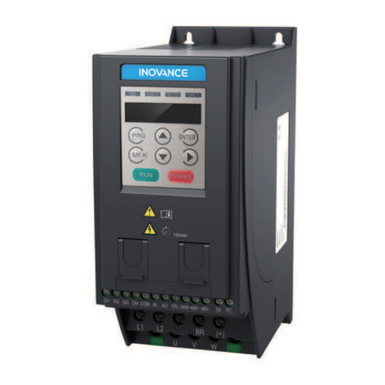
- Page 1 User Guide MD200 AC Drive General Purpose, Open Loop User Guide Data code 19010379...
-
Page 2: Table Of Contents
Contents Safety Information and Precautions ....................2 1 Product Information ........................4 1.1 Nameplate and Designation Rule ....................... 4 1.2 General Specifications ..........................5 1.3 Technical Specifications ..........................8 1.4 Environment..............................9 1.5 EMC Filter ..............................9 1.5.1 Internal (Built-in) EMC Filter............................9 1.5.2 External EMC Filter ................................9 1.6 Reactor ............................... -
Page 3: Safety Information And Precautions
Safety Information and Precautions This guide is packaged together with the product for MD200 AC Drive. It contains basic information for quick start of the drive. For safety and more information, please refer to the MD200 AC Drive User Manual, which can be downloaded on website: http://www.inovance. - Page 4 This manual provides a complete list of the parameters with functional description and care should always be taken whenever parameters are adjusted during a live runningstartup. Inovance Technology and Authorized Distributors can provide product trainingand if in doubt seek advice.
-
Page 5: Product Information
INPUT: Rated input PH AC 200-240V 18.0A 50Hz/60Hz OUTPUT: Rated output 3PH AC 0-240V 8.0A 0-500Hz 1.5kW S/N code S/N: Serial Number Suzhou Inovance Technology Co., Ltd. Manufacturer MD200 -INT MD200 series AC drive Mark Version Mark Built-in Braking Unit... -
Page 6: General Specifications
1 Product Information 1.2 General Specifications Voltage class 200 VAC to 240 VAC Model: MD200SxxB(1) 0.75 Dimension(2) Height, Width, Depth [H]: 160 mm, [H1]: 180 mm, [W]: 75 mm, [D]: 145 mm Mounting Hole, [mm] Φ5.0 Rated Input voltage 1 PH, 200 VAC to 240 VAC , -15% to +10% Rated input current, [A] 11.0 18.0... - Page 7 1 Product Information Voltage class 200 VAC to 240 VAC Model: MD200SxxB-NC(1) 0.75 Dimension(2) Height, Width, Depth [H]: 160 mm, [H1]: 180 mm, [W]: 75 mm, [D]: 145 mm Mounting Hole, [mm] Φ5.0 Rated Input voltage 1 PH, 200 to 240 VAC , -15% to +10% Rated input current, [A] 11.0 18.0...
- Page 8 1 Product Information Note (1): "B" denotes built-in brake unit. (2): The dimensions are shown as below: ENTER MF.K STOP/RES - 7 -...
-
Page 9: Technical Specifications
1 Product Information 1.3 Technical Specifications Items Specification Highest frequency V/F control: 0 to 500 Hz, SVC control: 0 to 500 Hz 0.8 kHz to 12 kHz, and able to automatically adjust carrier frequency based on Carrier frequency load characteristic Input frequency resolution Digital settings: 0.01 Hz;... -
Page 10: Environment
1 Product Information 1.4 Environment Environment conditions Indoor, keep away from direct sunlight, no dust, corrosive gas, flammable gas, oil mist, water vapor, water or salt, for instance. Altitude Use below 1000 m. The drive power derates 1% at every 100 m altitude increase. The highest allowed altitude is 3000 m. -
Page 11: Reactor
1.6.1 Input AC Reactor For MD200 series drives with power greater than 1kW, an AC reactor should be connected at the input power terminals to reduce the current harmonics, to be able to comply with the limits of IEC 61000-3-2 and IEC 61000-3-12 standards. For more information about the suitable AC reactor, consult your agent of Inovance. - Page 12 1 Product Information Dimensions of the output reactor models: Drive Model RWK 305-4-KL max.60 max.115 4.8×9 2.5 mm RWK 305-7.8-KL max.60 max.115 4.8×9 2.5 mm RWK 305-10-KL max.70 max.115 4.8×9 2.5 mm RWK 305-14-KL max.70 max.135 5×8 2.5mm - 11 -...
-
Page 13: Mechanical Installation And Wiring
Mechanical Installation and Wiring 2 Mechanical Installation and Wiring 2.1 Mechanical Installation The AC drive must be installed in a noncombustible cabinet that provides effective electrical and mechanical protection for CE requirements. Installation must conform to local and regional laws and regulations, and to relevant IEC requirements. 2.1.1 Installation Environment Item Requirements... -
Page 14: Cabinet Layout
Mechanical Installation and Wiring 2.1.2 Cabinet Layout The following figures show the cabinet layout, showing the recommended clearance around the MD200 drive. ≥10 ≥ 40 ≥100 ENTER MF.K STOP/RES ≥100 ≥10 Vertical Unit: mm Installation Installing a single drive ENTER MF.K... -
Page 15: Installation Method
Mechanical Installation and Wiring 2.1.3 Installation Method The following figures describe the installation method. Bracket slot of guide rail Bracket slot of guide rail Tightening screw Installing guide rail Note Tighten all screws according to the specified tightening torque. - 14 -... -
Page 16: Wiring
Note: The wiring in dotted line frame is for single-phase drive Breaker Fuse Single-phase input Three-phase input MD200 External operating panel Forward run F4-00 = 1 (keypad & display) Forward jog F4-01 = 4 Default value 1: OFF, 2: OFF, 3: OFF... -
Page 17: Terminal Description
Note: The wiring in dotted line frame is for the single-phase drive. Breaker Fuse Single-phase input Three-phase input MD200 External operating panel F4-00 = 1 DIP Switch Forward run Default value F4-01 = 4 1: ON, 2: ON Forward jog... - Page 18 Mechanical Installation and Wiring Terminal Terminal Name Description R, S, T Three-phase supply input Connect to the three-phase AC power supply. BR, (+) Braking resistor connection Connected to an external braking resistor. U, V, W Output terminals Connect to a three-phase motor. Ground (PE) Grounding connection.
- Page 19 Mechanical Installation and Wiring MD200XXX-NC Main Control Board Terminals ■ DIP switch Default value:1: ON, 2: ON DIO used Valid when the DI is as DI connected to 0 V Valid when the DI is DIO used connected to 24 V as DO Terminal Mark Terminal Name Function...
-
Page 20: Removing The Emc And Vdr Screws
Mechanical Installation and Wiring 2.2.3 Removing the EMC and VDR Screws To prevent personnel injury or damage to the equipment, you must ensure mains power is off before you start. WARNING If the drive is applied in an IT system, remove the EMC and VDR screws as shown in the following figures. VDR Jumper screw EMC Jumper... -
Page 21: Operating Panel
3 Operating Panel 3 Operating Panel 3.1 Getting Familiar with Operating Panel Overview ■ Status Indicators ∀ ∀ REMOTE FWD/ REV ∀ Keys ∀ TUNE/TC REMOTE FWD REV TUNE / TC ∀ ∀ MF.K ∀ ENTER ∀ ∀ STOP/ RES ∀... - Page 22 3 Operating Panel Key Name Function Perform a function switchover as defined by the setting of F7-01, for example to quickly switch Multifunction MF.K command source or direction. Status Indicators ■ There are four red LED status indicators at the top of the operating panel. Indicator Indication ON indicates the RUNNING status.
-
Page 23: Quick Setup
Parameter Name Default Commission Before power on Install and cable the drive. Install and cable the drive as explained in chapters 1 to 3 of the MD200 AC Drives User Manual. Check wirings. of power supply and AC drive outputs Restore parameters. - Page 24 4 Quick Setup START Para. Parameter Name Default Commission Set motor parameters. Motor Nameplate F1-01 Rated motor power model dependent Unit: kW F1-02 Rated motor voltage model dependent Unit: V F1-03 Rated motor current model dependent Unit: A F1-04 Rated motor frequency model dependent Unit: Hz F1-05...
- Page 25 4 Quick Setup CONTINUE Para. Parameter Name Default Commission If F0-08 is frequency reference Set F0-08 F0-08 Preset frequency 50.00 0 Hz to F0-10 If AI is frequency reference Set AI F4-13 AI curve minimum input 0.00 0 V to F4-15; F4-14 Corresponding percentage of AI minimum input...
- Page 26 4 Quick Setup F4-00 DI1 function selection 30: Pulse input as frequency reference (valid only for DI4) 32: Immediate DC injection braking 33: External fault normally-closed input 34: Frequency modification enabled 35: PID operation direction reverse 36: External stop 1 37: Command source switchover 2 38: PID integral disabled 39: Switchover between main frequency reference and preset frequency...
- Page 27 4 Quick Setup Set the DO function. F5-02 Relay function selection(T/A-T/C) 31: AI input exceeding limit 32: Load lost 33: Reverse running 34: Zero current 36: Output current exceeding limit 37: Frequency lower limit reached (having output at stop) 38: Alarm output 40: Current running time reached If an analog output is used 41: Fault output...
- Page 28 4 Quick Setup CONTINUE Para. Parameter Name Default Commission Set V/F parameters. F3-00 V/F curve selection 0: Linear V/F 1: Multi-point V/F F3-01 Torque boost 0.0 to 30.0 %; NOTE: If it is 0, automatic torque boost is activated, which is recommended. F3-02 Frequency limit of torque boost 50.00...
-
Page 29: Parameter Table
5 Parameter Table 5 Parameter Table 5.1 Introduction Groups F and A include standard function parameters. Group U includes the monitoring function parameters and extension card communication parameters. 5.2 Standard Parameters Para. No. Para. Name Setting Range Default Comms. Address Group F0: Standard Parameters 0: Sensorless vector control (SVC) F0-01... - Page 30 5 Parameter Table Para. No. Para. Name Setting Range Default Comms. Address 0.00 to 650.00s (F0-19=2) Model F0-18 Deceleration time1 0.0 to 6500.0s (F0-19=1) 0xF012/0x0012 dependent 0 to 65000s (F0-19=0) 0: 1s Acceleration/deceleration time F0-19 1: 0.1s 0xF012/0x0013 unit 2: 0.01s 0: Not retentive Retentive of digital setting F0-23...
- Page 31 5 Parameter Table Para. No. Para. Name Setting Range Default Comms. Address 0: F2-10 1: AI 2: External operating panel Torque limit source in speed F2-09 4: Pulse reference (DI5) 0xF209/0x0209 control 5: Serial communication 6: Minimum (AI1, AI2) 7: Maximum (AI1, AI2) Digital setting of torque limit in F2-10 0.0% to 200.0%...
- Page 32 5 Parameter Table Para. No. Para. Name Setting Range Default Comms. Address 0.0%: automatic torque boost F3-01 Torque boost 0.0% 0xF301/0x0301 0.1% to 30% F3-02 Cut-off frequency of torque boost 0.00 Hz to maximum frequency 50.00 Hz 0xF302/0x0302 F3-03 Multi-point V/F frequency 1 0.00 Hz to F3-05 0.00 Hz 0xF303/0x0303...
- Page 33 5 Parameter Table Para. No. Para. Name Setting Range Default Comms. Address Group F4: Input Terminals 0: No function 1: Forward run (FWD) 2: Reverse run (REV) 3: Three-wire control 4: Forward jog (FJOG) 5: Reverse jog (RJOG) F4-00 DI1 function selection 0xF400/0x0400 6: Terminal UP 7: Terminal DOWN...
- Page 34 5 Parameter Table Para. No. Para. Name Setting Range Default Comms. Address F4-13 AI curve1 min. input 0.00 V to F4-15 0.00 V 0xF40D/0x040D Corresponding percentage of AI F4-14 -100.00% to 100.0% 0.0% 0xF40E/0x040E curve 1 min. input F4-15 AI curve 1 max. input F4-13 to 10.00 V 10.00 V 0xF40F/0x040F...
- Page 35 5 Parameter Table Para. No. Para. Name Setting Range Default Comms. Address Setting selection when external operating panel Setting selection when AI less potentiometer less than F4-34 0xF422/0x0422 than min. input min. input 0: Corresponding percentage of min. input 1: 0.0% Setting selection when AI less than min.
- Page 36 5 Parameter Table Para. No. Para. Name Setting Range Default Comms. Address Group F5: Output Terminals 0: No output 1: AC drive running 2: Fault output 3: Frequency level detection 1 output 4: Frequency reached 5: Zero-speed running (no output at stop) 6: Motor overload pending F5-02 Relay (T/A-T/C) function selection...
- Page 37 5 Parameter Table Para. No. Para. Name Setting Range Default Comms. Address DIO active mode: Positive logic Negative logic F5-22 DO active mode selection 1 0000 0xF516/0x0516 Reserved Relay 1 active mode: Positive logic Negative logic Reserved Group F6: Start/Stop Control 0: Direct start F6-00 Start mode...
- Page 38 5 Parameter Table Para. No. Para. Name Setting Range Default Comms. Address Group F7: Keypad Operation and LED Display 0: Disabled F7-00 LED default display check 0xF700/0x0700 1: Enabled 0: MF.K key disabled 1: Switchover from remote control (terminal or communication) to keypad control 2: Switchover between forward rotation and F7-01...
- Page 39 5 Parameter Table Para. No. Para. Name Setting Range Default Comms. Address 0000 to 1FFF Frequency reference (Hz) Bus voltage (V) DI state DO state AI voltage (V) Reserved External operating panel potentiometer voltage (V) Count value F7-05 LED display stop parameters 0033 0xF705/0x0705 15 14...
- Page 40 5 Parameter Table Para. No. Para. Name Setting Range Default Comms. Address 0: Disabled F8-13 Reverse RUN selection 0xF80D/0x080D 1: Enabled 0: Run at frequency reference lower limit Running mode when frequency F8-14 reference lower than frequency 1: Stop 0xF80E/0x080E lower limit 2: Run at zero speed Accumulative power-on time...
- Page 41 5 Parameter Table Para. No. Para. Name Setting Range Default Comms. Address Output power correction F8-54 0.0% to 200.0% 100.0% 0xF836/0x0836 coefficient F8-55 Emergency deceleration time 0.0 to 6500.0 s 10.0s 0xF837/0x0837 0: Disabled Speed synchronous control F8-57 0xF839/0x0839 selection 1: Enabled It selects whether to enable the speed synchronous control function.
- Page 42 5 Parameter Table Para. No. Para. Name Setting Range Default Comms. Address F9-14 1st fault type 0: No fault 0xF90E/0x090E 1: Reserved F9-15 2nd fault type 0xF90F/0x090F 2: Overcurrent during acceleration 3: Overcurrent during deceleration 4: Overcurrent at constant speed 5: Overvoltage during acceleration 6: Overvoltage during deceleration 7: Overvoltage at constant speed...
- Page 43 5 Parameter Table Para. No. Para. Name Setting Range Default Comms. Address F9-32 AC drive state upon 2nd fault 0xF920/0x0920 F9-33 Power-on time upon 2nd fault 0xF921/0x0921 F9-34 Running time upon 2nd fault 0xF922/0x0922 F9-37 Frequency upon 1st fault 0xF925/0x0925 F9-38 Current upon 1st fault 0xF926/0x0926...
- Page 44 5 Parameter Table Para. No. Para. Name Setting Range Default Comms. Address FA-01 PID digital setting 0.0% to 100.0% 50.0% 0xFA01/0x0A01 0: AI 1: External operating panel potentiometer 3: Ai - external operating panel potentiometer 4: PULSE reference (DI4) 5: Via communication FA-02 PID feedback setting channel 0xFA02/0x0A02...
- Page 45 5 Parameter Table Para. No. Para. Name Setting Range Default Comms. Address 00 to 11 Whether to stop integral operation when PID output FA-25 PID integral property 0xFA19/0x0A19 reaches the limit 0: Continue integral operation 1: Stop integral operation Integral separation 0: Disabled 1: Enabled 0%: No detection...
- Page 46 5 Parameter Table Para. No. Para. Name Setting Range Default Comms. Address 00 to 11 Retentive selection at FC-17 Simple PLC retentive selection 0xFC11/0x0C11 power down 0: Not retentive 1: Retentive Retentive selection at stop 0: Not retentive 1: Retentive Running time of simple PLC FC-18 0.0s (h) to 6500.0s (h)
- Page 47 5 Parameter Table Para. No. Para. Name Setting Range Default Comms. Address Group Fd: Communication 0000 to 5009 CANlink baud rate: 0: 20 Kbps 1: 50 Kbps 2: 100 Kbps 3: 125 Kbps 4: 250 Kbps 5: 500 Kbps Reserved Fd-00 Baud rate 5005...
- Page 48 5 Parameter Table Para. No. Para. Name Setting Range Default Comms. Address Group FE: User-defined Parameters FE-00 User-defined parameter 0 F0.00 0xFE00/0x0E00 FE-01 User-defined parameter 1 F0.00 0xFE01/0x0E01 FE-02 User-defined parameter 2 F0.00 0xFE02/0x0E02 FE-03 User-defined parameter 3 F0.00 0xFE03/0x0E03 FE-04 User-defined parameter 4 F0.00...
- Page 49 5 Parameter Table Para. No. Para. Name Setting Range Default Comms. Address Group FP: Function Parameter Management FP-00 User password 0 to 65535 0x1F00 0: No operation 01: Restore factory parameters except motor parameters 02: Clear records 03: Reserved 04: Back up current user parameters FP-01 Industry macro 0x1F01...
- Page 50 5 Parameter Table Para. No. Para. Name Setting Range Default Comms. Address 00000 to 11111 VDI5: 0: Inactive 1: Active VDI4: A1-06 Selection of VDI active state 00000 0xA106/0x4106 0: Inactive 1: Active VDI3: 0: Inactive 1: Active VDI2: 0: Inactive 1: Active VDI1: 0: Inactive...
- Page 51 5 Parameter Table Para. No. Para. Name Setting Range Default Comms. Address 00000 to 11111 VDO5: 0: Positive logic active 1: Negative logic active VDO4: 0: Positive logic active A1-21 VDO active mode selection 00000 0xA115/0x4115 1: Negative logic active VDO3: 0: Positive logic active 1: Negative logic active...
- Page 52 5 Parameter Table Para. No. Para. Name Setting Range Default Comms. Address SVC magnetic field open loop AA-08 30% to 150% 0xAA08/0x4A08 control low speed current Open loop control switchover AA-09 2.0 to 100.0 Hz 4.0 Hz 0xAA07/0x4A07 frequency Open loop control deceleration AA-10 0 to 6 0xAA0A/0x4A0A...
-
Page 53: Monitoring Parameters
5 Parameter Table 5.3 Monitoring Parameters Para. No Para. Name Comms. Address Group U0: Monitoring Parameters U0-00 Running frequency 0x7000 U0-01 Frequency reference 0x7001 U0-02 Bus voltage 0x7002 U0-03 Output voltage 0x7003 U0-04 Output current 0x7004 U0-05 Output power 0x7005 U0-06 Output torque 0x7006... - Page 54 6 Troubleshooting Para. No Para. Name Comms. Address Group U0: Monitoring Parameters U0-62 Current fault code 0x703E U0-63 Reserved 0x703F U0-64 Number of slaves 0x7040 U0-65 Torque upper limit 0x7041 U0-69 Speed of transmitting DP 0x7045 U0-71 Communication card current display 0X7047 U0-78 Linear speed...
-
Page 55: Troubleshooting
6 Troubleshooting 6 Troubleshooting 6.1 AC Drive Performance Fine Tuning Frequency setpoint Time Stop Nominal speed Deceleration Start Acceleration Stage Symptom Diagnostics Remedies The start frequency is too low. Increase F6-03, ranging from 0 to10 Hz Rollback Start The output torque is insufficient. Make sure F3-00 = 0, F3-01 = 0 Starting jerk The start frequency is too high. -
Page 56: Fault Codes And Troubleshooting
6 Troubleshooting 6.2 Fault Codes and Troubleshooting Display Fault Name Possible Causes Solutions Ground fault or short circuit exists in the output Check whether short-circuit occurs on the motor, circuit. the motor cable or contactor. Acceleration time is too short. Increase acceleration time. - Page 57 Eliminate faults in external circuitry. Drive board is abnormal. Input phase loss Lightning protection board is abnormal. Contact the agent or Inovance. Control board is abnormal. Check resistance between motor cables. Motor winding is damaged. Replace motor is winding is damaged.
- Page 58 6 Troubleshooting Display Fault Name Possible Causes Solutions Accumulative Accumulative running time reaches the setting running time Clear the record through parameter initialization. value. reached User-defined fault 1 is input via DI. User-defined fault 1 Reset the operation. User-defined fault 1 is input via virtual I/O. User-defined fault 2 is input via DI.
-
Page 59: Symptoms And Diagnostics
Set motor parameters or perform motor auto-tuning again. The AC drive detects The acceleration or deceleration time is too overcurrent and Set proper acceleration or deceleration time. short. overvoltage frequently. Load fluctuates. Contact the agent or Inovance. - 58 -... -
Page 60: Revision History
Revision History Date Version Change Description Jan 2016 V0.0 Related firmware version: F7-10 = U10.05 and F7-11 = U0.06 Mar 2016 Related firmware version: F7-10 = U10.06 and F7-11 = 001.00 Modified Approvals, designation rule and nameplate. Nov 2016 Added information of three-phase models. Modified information of three-phase models. - Page 61 Service Hotline: 400-777-1260 http: //www.inovance.com Suzhou Inovance Technology Co., Ltd. Add.: No. 16 Youxiang Road, Yuexi Town, Wuzhong District, Suzhou 215104, P.R. China Tel: +86-512-6637 6666 Fax: +86-512-6285 6720 Service Hotline: 400-777-1260 http: //www.inovance.com Copyright Shenzhen Inovance Technology Co., Ltd.
Need help?
Do you have a question about the MD200 and is the answer not in the manual?
Questions and answers