Table of Contents
Advertisement
Quick Links
DIGITAL DUST INDICATOR
O P E R A T I O N M A N U A L
This operation manual describes precautions that are important for preventing accidents as
well as procedures used to handle the product.
Read this operation manual and the attached warranty thoroughly before use, and use the
product correctly.
After reading this operation manual and the warranty, keep them handy for future reference.
Thank you for purchasing this product.
CODE 080000-73
Advertisement
Table of Contents

Related Manuals for Sibata LD-5R


Summary of Contents for Sibata LD-5R
- Page 1 CODE 080000-73 DIGITAL DUST INDICATOR O P E R A T I O N M A N U A L Thank you for purchasing this product. This operation manual describes precautions that are important for preventing accidents as well as procedures used to handle the product. Read this operation manual and the attached warranty thoroughly before use, and use the ...
-
Page 2: Table Of Contents
Table of Contents Before Use ......................4 Safety Precautions ....................4 About This Product ..................7 1-1 Overview ........................7 1-2 Main Features ......................7 1-3 Product Contents ....................... 8 1-4 Attaching the Shoulder Belt ..................8 Description of the Parts .................. 9 Description of the Main Screens and Parts .......... - Page 3 Measurements) ....................28 8-3-3 Timed Measurement Modes ................29 8-3-4 Timed Measurement Mode—Setting a User Designated Measurement Time . 30 8-3-5 Manual Measurement Mode ................31 8-4 Starting the Measurement ..................31 8-5 During Measurement ....................32 8-5-1 LCD Screen Sleep Function ................33 8-6 Finishing the Measurement ..................
-
Page 4: Before Use
The copyright of this operation manual belongs to Sibata Scientific Technology Ltd. This operation manual, or any part thereof, may not be reproduced, reprinted, or altered in any form without prior written permission from Sibata Scientific Technology Ltd. Safety Precautions... - Page 5 If it is determined that the product caused the problem, turn OFF the power switch, disconnect the AC adapter from the power outlet, and then contact your Sibata representative. Never operate the product if it is not functioning normally. Also, never allow anyone other than a qualified service engineer to disassemble or modify the product.
- Page 6 OFF the power switch, disconnect the power cord from the power outlet, and then contact your Sibata representative. Please be aware that in the unlikely event of a product failure, Sibata bears no responsibility to compensate for data not acquired or recorded, and is not responsible for loss of data or for other direct or indirect damages incurred from such loss.
-
Page 7: About This Product
1 About This Product Overview This product is a dust indicator that makes use of scattered laser light. When airborne dust in a darkened room is irradiated with light, if the physical properties of the dust are kept under the same conditions, the amount of light scattered by the dust is proportional to the mass concentration. -
Page 8: Product Contents
Product Contents Check the package contents before using the product. ································································ LD-5R main unit AC adapter (with four types of adapter plugs) ···································· 1 AA alkaline batteries (for checking operations) ··································· 6 Shoulder belt ·············································································· 1 ... -
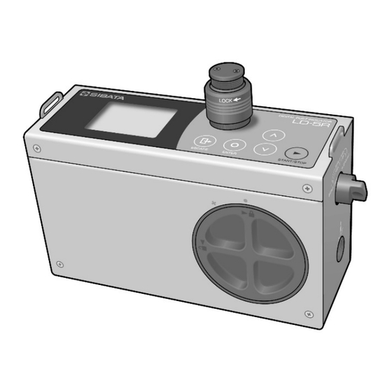
Page 9: Description Of The Parts
Standby and stopped (measurements finished): Orange, flashing Measuring: Green, flashing → See 8-5-1 LCD Screen Sleep Function. The DC jack shape is different than on models up to LD-5R Ver. 1.03 (Item Code 080000-72). The AC adapter is also different. - Page 10 Bottom of the Main Unit ⑬ Purge filter cover (PURGE FILTER) ⑭ Pump filter cover (PUMP FILTER) ⑮ Tripod attachment screw (TRI POD) Main Unit Panel ⑯ [ESCAPE] switch ⑰ [ENTER] switch ⑱ [UP] switch ⑲ [DOWN] switch ⑳ [START/STOP] switch...
-
Page 11: Description Of The Main Screens And Parts
3 Description of the Main Screens and Parts Screens During Measurement The display items for each part change with the screen and operation. During measurement, press the [UP] or [DOWN] switch to toggle the screens. Instantaneous Value Graph Display Trend Graph Display Dual Display... -
Page 12: Standby Screens
Standby Screens When the power switch is turned ON, the startup screen ( ) is displayed and then the BG (background) measurement /standby ( green) screen is displayed. This screen is divided into two types: measurement mode and setting mode. Press the [UP] or [DOWN] switch to toggle the modes in sequence. -
Page 13: Measurement Mode Screens
3-2-1 Measurement Mode Screens BG Measurement/Standby BG Measurement/Measuring SPAN Measurement/Standby SPAN Measurement/Measuring 1 Minute Measurement/Standby 1 Minute Measurement/Measuring Timed Measurement/Setting Timed Measurement/Start Standby Manual Measurement/Standby Manual Measurement/Measuring In this manual, some of the notation (guidance, current time, etc.) in the screens shown ... -
Page 14: Setting Modes
3-2-2 Setting Modes Only the items are displayed in the standby screen. Press the [ENTER] switch to move to the setting screen and display the setting details. The setting details displayed, with some exceptions, can be changed by pressing the [ENTER] switch. Screen Details for Log Setting Mode 00. - Page 15 Screen Details for Basic Setting Mode Version of main unit and LCD 00. Version Example: Ver 2.00 ED4 008 YYYY / MM / DD hh : mm : ss 01. Set Clock 02. Set Kfactor 0.01 to 999.99 03. SPAN Value 04.
-
Page 16: Description Of Icons
3-2-3 Description of Icons The meaning of the icons in the LCD screen and panel sheet is as per the table below. Name and Icon Name and Status Icon Icon Name and Status Status Standby (green) ESCAPE Timer meter Measuring (orange) ENTER Free mark Measurement... -
Page 17: Screen Displayed When The Measurement Is Finished
3-2-4 Screen Displayed When the Measurement Is Finished During measurement, press the [START/STOP] switch to finish the measurement. After the measurement is finished, accumulated count is displayed. After the BG measurement is finished, the instantaneous value graph is displayed. After the SPAN measurement is finished, the screen changes to dual display. -
Page 18: Remaining Battery Level Display
3-2-5 Remaining Battery Level Display The battery level indicator shows the remaining battery level, from 100 to 0 %. (% may not be displayed depending on the screen.) The battery level is only a guide. Be sure to check the remaining battery level during measurement (when the pump is operating). -
Page 19: Backup Battery
(2) Insert six AA batteries into the battery case. (Alkaline batteries are recommended.) With alkaline batteries, the instrument can be used continuously for approximately 10 hours*. * When the LCD is turned OFF by the sleep function. The factory default turns OFF the LCD 90 seconds after the last switch operation. -
Page 20: Ac Power Supply
[PUSH] button. (3) Connect the AC adapter's DC plug to the DC jack on the LD-5R. (4) Plug the AC adapter's AC plug into an AC power outlet. When the AC adapter is connected, power ... -
Page 21: Replacing The Filters
18. Reset operating time. O-ring → See 9-4 Basic Setting Mode—18. Reset operating time. Pump filter: High-Performance Backup Filter for LD-5R (Item Code 080000-7202) The purge filter should be replaced about once per year. Knob Place the coarse end of the purge filter ... -
Page 22: Attaching The Filter Covers
(2) Align the dot (●) mark on the filter cover with the circle (○) mark on the bottom of the LD-5R unit and turn the cover clockwise. Note: Be careful not to insert the cover at an angle. -
Page 23: Operating The Air Sampling Port Cap
6 Operating the Air Sampling Port Cap The air sampling port is the intake for the sample air (dust). It has a cap that opens and closes. Operation of the air sampling port cap is necessary in the following cases. ... -
Page 24: Operating The Scattering Plate Knob
7 Operating the Scattering Plate Knob Operation of the scattering plate knob is required in the following cases. During BG measurement and dust measurement During SPAN measurement → See 8-2-2 BG Measurement Mode—BG Subtraction Function. → See 8-2-3 SPAN Measurement Mode—Sensitivity Correction. During BG Measurement and Dust Measurement Move the scattering plate knob to the... -
Page 25: Measuring Samples
8 Measuring Samples Measurement Procedures The basic measurement procedures are as follows. Turn ON the power switch. Close the air sampling port cap. Turn the scattering plate knob to [MEASURE]. Perform the BG measurement (8 seconds + 6 seconds). Turn the scattering plate knob to [SENSI. ADJ.]. Perform the SPAN measurement (60 seconds). -
Page 26: Preparing For The Measurement
SPAN measurement mode screen is displayed. When the LD-5R power is ON, the LED indicator flashes orange. This indicates that the sleep function is not enabled. Press any switch to enable the sleep function. → See 8-5-1 LCD Screen Sleep Function. -
Page 27: Span Measurement Mode-Sensitivity Correction
The BG measurement can be aborted by pressing the [START/STOP] switch twice during the 6 second measurement interval. If this is performed, the BG subtraction function does not operate during the next dust measurement. 8-2-3 SPAN Measurement Mode—Sensitivity Correction The measurement sensitivity of dust indicators can vary due to contamination inside the detector, deterioration of electrical parts, misaligned optical components caused by vibration, or other factors. -
Page 28: Selecting The Measurement Mode
If standby is selected in timed measurement mode, when measuring dust, first turn the scattering plate knob to the [MEASURE] position. Selecting the Measurement Mode When the power switch is turned ON, the BG measurement/standby ( green) screen is displayed. This screen is divided into two types: measurement mode and setting mode. -
Page 29: Timed Measurement Modes
8-3-3 Timed Measurement Modes Measurement starts at the set start date and finishes automatically after the set measurement time has elapsed. (1) In the timed measurement mode/standby ( green) screen, press the [ENTER] switch. (2) The setting screen ( blue) is displayed and a pointer is displayed to the left of the measurement time. - Page 30 8-3-4 Timed Measurement Mode—Setting a User Designated Measurement Time In timed measurement mode, pressing the [START/STOP] switch without setting [02. Start Date] enables measurement with a user designated countdown timer measurement time different from the existing countdown timer settings (1 minute, 2 minutes, 10 minutes, 60 minutes, and 240 minutes).
-
Page 31: Manual Measurement Mode
8-3-5 Manual Measurement Mode In this mode, measurement is started and stopped by pressing the [START/STOP] switch. In the timer display area, the elapsed measurement time is displayed. The timer meter is not displayed. Starting the Measurement Turn the scattering plate knob to the [MEASURE] position. -
Page 32: During Measurement
During Measurement During measurement ( orange), press the [UP] or [DOWN] switch to toggle the instantaneous value graph display, the trend graph display, and the dual graph display. Instantaneous Value Graph Display Trend Graph Display Dual Display Accumulated Count The value of the accumulated count in the display is five digits (99999) long. If this is exceeded, it returns to 0 and measurement continues. -
Page 33: Lcd Screen Sleep Function
LED indicator. Restoring the LCD " Press any switch once to display LD-5R Restoring LCD" and to turn ON the LCD again. The function of the switch pressed is disabled. Press the intended switch ... -
Page 34: Finishing The Measurement
Finishing the Measurement 8-6-1 Countdown Timer Measurements and Timed Measurements After the measurement time has elapsed, measurement stops automatically. During measurement, press the [START/STOP] switch to finish the measurement at that point. After measurement is finished, the screen changes to the instantaneous value graph display and the measurement results is displayed. -
Page 35: Functions
9 Functions Mass Concentration Conversion This product is equipped with a function to convert the relative concentration to mass concentration based on a preset mass concentration conversion coefficient (hereinafter the "K factor"), and display the result. To convert the display to the mass concentration, it is necessary to configure the or μg/m units to mg/m as per 9-4-2 Description of the Setting Items—05. -
Page 36: Entering The K Factor
Entering the K Factor In the dust indicator, 1 CPM is preset to 0.001 (mg/m ) for standard particles. Accordingly, to actually enter (configure) the K factor determined earlier into the dust indicator, the value to enter must be further calculated from the following formula. -
Page 37: Log Recordings
(4) Press the [UP] or [DOWN] switch to move the pointer . Then press the [ENTER] switch to display the content of the data. Sample Display: Data for Log Number 00 Data Number Measurement Start Time 00000 16:25:05 00023 00001 16:25:06 00021 00002... -
Page 38: Erasing The Log
(5) If you do not wish to delete the data, press the [ESCAPE] switch. Note: Please be aware that in the unlikely event of a product failure, Sibata bears no responsibility to compensate for data not acquired or recorded, and is not responsible for loss of data or for other direct or indirect damages incurred from such loss. -
Page 39: Basic Setting Mode
Basic Setting Mode This mode is used to check the values of various setting items and to change settings. The items are divided across multiple screens. 9-4-1 Operation (1) In the basic setting mode/standby ( green) screen, press the [ENTER] switch. -
Page 40: Description Of The Setting Items
9-4-2 Description of the Setting Items This displays the LD-5R main unit firmware version and the 00. Version LCD version. The LCD version is not shown in some cases. 01. Set Clock This is used to set the date and current time. - Page 41 This is used to change the scale of the vertical axis of the 11. Graph YAxis trend graph. Scale Selection items: AUTORANGE, 0-100CPM, 0-1000CPM, 0-10000CPM Factory default: AUTORANGE 12. Voutput Zero This is used to adjust the zero point for the 0 to 1 V output. Adj.
-
Page 42: Communication Specifications
The output data can be imported to a PC with commands from the terminal software. The special LD-5R USB driver and USB cable (A-mini B) are required for the USB connection. The USB driver is available for download from the Sibata website. -
Page 43: Communication Commands And Control
If ">49 Return to BG measurement mode" is not transmitted, commands to move to other measurement modes will not be received. Transmitting “>49 Return to BG measurement mode” with the scattering plate knob in the [SENSI.ADJ.] position could cause a problem. 10-3-1 Reading Commands LD-5R Command Returns >04 Menu display >04,nn... - Page 44 LD-5R Command Returns Log index continued ,Log number (00-49) ,YYYY,MM,DD,hh,mm,ss Start date ,nnnnnnn Number of data points ,hhhh,mm,ss Measurement time (0000-9999,00-59,00-59) ,mm,ss Logging cycle (00-60,00-59) *Outputs all contents of a log index. >26,nn Log data >26,nnnnn 00-49 ,nnnnn ,nnnnn ,nnnnn *Outputs all contents of log data.
-
Page 45: Operating Commands
10-3-2 Operating Commands LD-5R Command Returns >03,nn Menu display >03,nn 00: BG measurement 02: 1min 03: 2min 04: 10min 05: 60min 06: 240min 08: Timed measurement 09: Manual measurement 10: Log setting 11: Basic setting >07 Start measurement >07 >10 Finish measurement >10... - Page 46 LD-5R Command Returns >28,nn,nn,nn LCD operation >28,nn,nn,nn Operation, sleep time , sleep time (seconds) (hundred seconds) 00: Sleep 00-99 00-06 (seconds) (hundred seconds) 01: Continuous * The sleep time setting can range from 15 seconds (15,00) to 600 seconds (00,06).
-
Page 47: Output Specifications (Output Connector)
11 Output Specifications (Output Connector) The optional analog pulse cable for the LD-5R (Item Code 080000-7204) is required to use the output function. Connector: 3540-16P-CV (50) (Hirose Electric brand) 11-1 Analog Output A voltage corresponding to the concentration during measurement is output (0 to 1 V/FS). -
Page 48: Troubleshooting
12 Troubleshooting If a problem occurs during use of the product, promptly stop using it. If the error has been caused by a product failure, do not use it again and request repair. Problems sometimes occur for reasons other than malfunction. Before requesting repair, check the following. - Page 49 Problem Cause Remedy Replace the backup lithium The current time has been The backup battery is battery. reset. depleted. See 4-2 Backup Battery. In log setting mode, delete the Data cannot be recorded. The memory is full. data. See 9-3-4 Erasing the Log. Close the air sampling port and perform the BG measurement several times.
-
Page 50: Specifications
13 Specifications Item Code 080000-73 Model LD-5R Measurement Light scattering Principle Light Source Laser diode Measurement 1 cpm = 0.001 mg/m (for standard particles) Sensitivity Measurement 0.001 to 10.000 mg/m Range Measurement ±10 % (for standard particles) Accuracy Intake Flowrate 1.7 L/min... - Page 51 Pump filter for LD-5R Glass Fiber Filters, PTFE Binding, 080130-098020 Purge filter TF98R, 20 mm dia., 100 pc Air Sampling Port with Seal for LD-5R 080000-72051 080870-54 AC Adapter UES36LCP Options Purchase these separately based on intended applications. Item Code...
-
Page 52: Precautions For Maintenance, Storage, And Transport
Sibata does not warrant any loss or damage to data recorded in memory. Therefore, always make a backup of necessary data. If you ignore the precautions in this manual or fail to create a backup, Sibata shall not be responsible for any damages resulting from lost or damaged data. -
Page 53: Warranty
15 Warranty If a Sibata product fails within one year from date of purchase, it will be repaired free of charge. To request repairs, contact your Sibata representative. Be sure to provide the item code, product name, model number, serial number, a description of the problem, and other relevant information. -
Page 54: Preferred Procedures For Requesting Repairs To Products Used In Environments Exposed To Asbestos
(3) If you are delivering the product to Sibata via courier, in addition to the product model number, enter "AS" in the "Details" and "Name of Goods" fields on the invoice. -
Page 55: Disclaimers
Therefore, always make a backup of necessary data before requesting repairs or other service work by Sibata. If you ignore the precautions in this manual or fail to create a backup, Sibata shall not be responsible for any damages resulting from lost or damaged data. - Page 56 Note) Shape, dimensions, specifications, and other product information are subject to change without notice in the interest of product improvement to the extent that product functions and applications will not be impaired.
Need help?
Do you have a question about the LD-5R and is the answer not in the manual?
Questions and answers