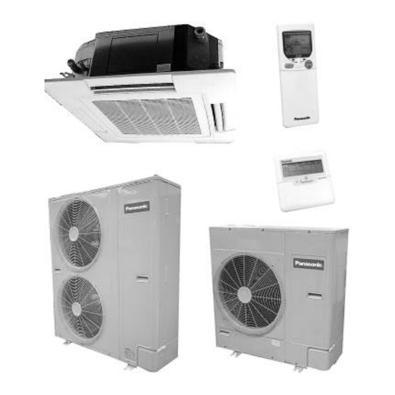
Panasonic CS-A24BB4P Service Manual
Cassette type
Hide thumbs
Also See for CS-A24BB4P:
- Operating instructions manual (25 pages) ,
- Service manual (153 pages)
Table of Contents
Advertisement
2001 Matsushita Air-Conditioning Corp. Sdn. Bhd. (183914D).
All rights reserved. Unauthorized copying and distribution is a
CS-A24BB4P / (CU-C24BBP5 / CU-A24BBP5)
CS-A28BB4P / (CU-C28BBP5 / CU-A28BBP5)
CS-A28BB4P / (CU-C28BBP8 / CU-A28BBP8)
CS-A34BB4P / (CU-C34BBP5 / CU-A34BBP5)
CS-A34BB4P / (CU-C34BBP8 / CU-A34BBP8)
CS-A43BB4P / (CU-C43BBP8 / CU-A43BBP8)
CS-A50BB4P / (CU-C50BBP8 / CU-A50BBP8)
1
ORDER NO. MAC0112071C0
AIR CONDITIONER
CASSETTE TYPE
Indoor Model / Outdoor Model
(Cooling / Heat Pump)
CS-A28BB4P / (CU-C28BBP6)
CS-A34BB4P / (CU-C34BBP7)
CS-A43BB4P / (CU-C43BBP7)
CS-A50BB4P / (CU-C50BBP7)
Advertisement
Table of Contents

Related Manuals for Panasonic CS-A24BB4P


Summary of Contents for Panasonic CS-A24BB4P
- Page 1 ORDER NO. MAC0112071C0 AIR CONDITIONER CASSETTE TYPE Indoor Model / Outdoor Model (Cooling / Heat Pump) CS-A24BB4P / (CU-C24BBP5 / CU-A24BBP5) CS-A28BB4P / (CU-C28BBP5 / CU-A28BBP5) CS-A28BB4P / (CU-C28BBP8 / CU-A28BBP8) CS-A28BB4P / (CU-C28BBP6) CS-A34BB4P / (CU-C34BBP5 / CU-A34BBP5) CS-A34BB4P / (CU-C34BBP8 / CU-A34BBP8)
-
Page 2: Service Information
violation of law. 1. SERVICE INFORMATION Notice of Address setting for NEW Cassette / NEW Outdoor Unit. The new Cassette / new Outdoor models are possible to have address setting for twin / triple control or group control automatically when main power supply is switched on. (Manual address setting is also possible by using DSW1 switch on the indoor unit P.C. - Page 3 - When making the replacement of units of master and slave etc. 1.2. Caution during test operation Do not touch the remote control button and do not change any wirings for one minute when the main power supply switch is ‘on’. / (Because the unit is having automatic address setting during the first one minute.) 1.3.
- Page 4 - Auto Swing Louvre / The air flow angle can be changed automatically (or manually) to an angle between 10° to 70° using the remote control. - Low ambient cooling operation / Cooling operation is possible at outdoor temperature of / -5°C. - Automatic changeover function (heat pump models) The unit automatically switches between cooling and heating in accordance with operating load in order to maintain a comfortable...
- Page 5 4. The heat exchanger has an L-shaped design to allow air to flow more smoothly. 5. Noise is automatically reduced further during night-time operation with lower outdoor air temperatures. 2.3. Greatly improved workability increases system renewal capability - Pipes that are one size larger can also be connected for renewal. - If renewing the system, existing refrigerant pipes can be utilized so that only the indoor and outdoor units need to be replaced.
- Page 6 30 m of pipe length. This makes installation much easier. - Drain water dripping-prevention structure - The base of the outdoor unit is provided with a single drain hole in order to prevent drain water from leaking out of the unit. By connecting a drain elbow and a discharge pipe, water leakages can be prevented even when the unit is installed to a wall.
- Page 7 2.4. A brand-new control method using the latest in technology - Easier power supply wiring connection / Power supply wiring and other wiring tasks can be carried out more easily. - Twin non-polar wires used to connect indoor and outdoor units. - Adoption of connection error prevention circuits for drive wires and signal wires.
- Page 8 connected and the connection methods, conditions such as the connection configuration (twin or triple format) and remote-control functions such as automatic louvre operation and cooling or heating mode are automatically detected and set instantly. 2.5. Wired Remote Control - The new design includes an easily-visible red pilot lamp. The power can be turned on and off at a single touch, without opening the cover.
- Page 9 - New design with compact size. (Operation range within approximately 8 m.) - Built-in timer with ON/OFF timer setting (within 24 hours) Wired Wireless Heat Pump CZ-RD51P CZ-RL51P Cooling CZ-RD51P CZ-RL01P NOTE: Both of the above remote control is packed separately from the indoor unit. 2.7.
-
Page 10: Specification (Heat Pump Type )
3. SPECIFICATION (HEAT PUMP TYPE ) 3.1. CS-A24BB4P / CU-A24BBP5 Indoor Unit Outdoor unit Main Body CS-A24BB4P CU-A24BBP5 ITEM / MODEL Panel CZ-BT01P Remote CZ-RD51P (Wired) Control CZ-RL51P (Wireless) Cooling Capacity BTU/h 21,500 Heating Capacity BTU/h 24,200 Refrigerant Charge-less Standard Air Volume for High,... - Page 11 Compressor T ype, Number of Set Hermetic-1 (Rotary), Starting Method Direct on-line starting Motor Type 2-pole single phase induction motor Input Cool/Heat 2.31 Rated Output Type, Number of Set Turbo fan-1 Propeller fan Motor Type 6-pole single phase 6-pole single phase induction motor induction motor Input...
- Page 12 CS-A24BB4P, CU-A24BBP5 ITEM / MODEL Condition by JIS B 8615 Volts Phase Single Single Single Power Consumption Cool 2.50 2.50 2.50 Heat 2.49 2.49 2.49 Running Current Cool 11.5 11.1 10.7 Heat 11.4 11.0 10.7 Starting Current Power Factor Cool Heat *Power Factor means total figure of compressor, indoor fan motor and outdoor fan motor.
- Page 13 Cool 12.3 12.0 11.7 Heat 12.0 11.7 11.4 Starting Current Power Factor Cool Heat *Power Factor means total figure of compressor, indoor fan motor and outdoor fan motor. Panasonic Power source AC, 1~220V, 230V, 240V 50Hz 3.3. CS-A28BB4P / CU-A28BBP8...
- Page 14 Indoor Unit Outdoor unit Main Body CS-A28BB4P CU-A28BBP8 ITEM / MODEL Panel CZ-BT01P Remote CZ-RD51P (Wired) Control CZ-RL51P (Wireless) Cooling Capacity BTU/h 24,200 Heating Capacity BTU/h 27,300 Refrigerant Charge-less Standard Air Volume for High, Hi 20 Me 18 Lo 16 Hi 43 /min Medium and Low Speed...
- Page 15 Cool 4.50 4.45 4.40 Heat 4.30 4.25 4.20 Starting Current Power Factor Cool Heat *Power Factor means total figure of compressor, indoor fan motor and outdoor fan motor. Panasonic Power source AC, 3N~380V, 400V, 451V 50Hz 3.4. CS-A34BB4P / CU-A34BBP5...
- Page 16 Indoor Unit Outdoor unit Main Body CS-A34BB4P CU-A34BBP5 ITEM / MODEL Panel CZ-BT01P Remote CZ-RD51P (Wired) Control CZ-RL51P (Wireless) Cooling Capacity 10.0 BTU/h 34,100 Heating Capacity 11.2 BTU/h 38,200 Refrigerant Charge-less Standard Air Volume for High, Hi 26 Me 23 Lo 20 Hi 70 /min...
- Page 17 16.9 17.0 Starting Current Power Factor Cool Heat *Power Factor means total figure of compressor, indoor fan motor and outdoor fan motor. Panasonic Power source AC, 1~220V, 230V, 240V 50Hz 3.5. CS-A34BB4P / CU-A34BBP8 Indoor Unit Outdoor unit Main Body...
- Page 18 O.D Ø 19.05 (3/4) Flared Type Piping Refrigerant Gas mm (inch) O.D Ø 9.52 (3/8) Flared Type Connection Liquid mm (inch) O.D Ø 20 I.D Ø 20 x Drain Compressor T ype, Number of Set Hermetic-1 (Rotary), Starting Method Direct on-line starting Motor Type 2-pole 3-phase induction...
- Page 19 5.80 5.80 Starting Current Power Factor Cool Heat *Power Factor means total figure of compressor, indoor fan motor and outdoor fan motor. Panasonic Power source AC, 3N~380V, 400V, 415V 50Hz 3.6. CS-A43BB4P / CU-A43BBP8 Indoor Unit Outdoor unit Main Body...
- Page 20 Heat 4.10 4.10 4.10 Running Current Cool Heat Starting Current Power Factor Cool Heat *Power Factor means total figure of compressor, indoor fan motor and outdoor fan motor. Panasonic Power source AC, 3N~380V, 400V, 415V 50Hz 3.7. CS-A50BB4P / CU-A50BBP8...
- Page 21 Indoor Unit Outdoor unit Main Body CS-A50BB4P CU-A50BBP8 ITEM / MODEL Panel CZ-BT01P Remote CZ-RD51P (Wired) Control CZ-RL51P (Wireless) Cooling Capacity 14.0 BTU/h 47,800 Heating Capacity 15.5 BTU/h 52,900 Refrigerant Charge-less Standard Air Volume for High, Hi 30 Me 27 Lo 24 Hi 86 /min...
-
Page 22: Specification (Cooling Only Type )
Cool Heat Starting Current Power Factor Cool Heat *Power Factor means total figure of compressor, indoor fan motor and outdoor fan motor. Panasonic Power source AC, 3N~380V, 400V, 415V 50Hz 4. SPECIFICATION (COOLING ONLY TYPE ) 4.1. CS-A24BB4P / CU-C24BBP5... - Page 23 Indoor Unit Outdoor unit Main Body CS-A24BB4P CU-C24BBP5 ITEM / MODEL Panel CZ-BT01P Remote CZ-RD51P (Wired) Control CZ-RL01P (Wireless) Cooling Capacity BTU/h 21,500 Refrigerant Charge-less Standard Air Volume for High, Hi 17 Me 15 Lo 14 Hi 43 /min Medium and Low Speed...
- Page 24 35°C D.B. (95°F D.B.), 24°C W.B. (75.2°F W.B.) ELECTRICAL DATA (50Hz) CS-A24BB4P, CU-C24BBP5 ITEM / MODEL Condition by JIS B 8615 Volts Phase Single Single Single Power Consumption Cool 2.50 2.50 2.50 Running Current Cool 11.5 11.1 10.7...
- Page 25 2.69 2.69 2.69 Running Current Cool 12.3 12.0 11.7 Starting Current Power Factor Cool *Power Factor means total figure of compressor, indoor fan motor and outdoor fan motor. Panasonic Power source AC, 1~220V, 230V, 240V 50Hz 4.3. CS-A28BB4P / CU-C28BBP6...
- Page 26 Indoor Unit Outdoor unit Main Body CS-A28BB4P CU-C28BBP6 ITEM / MODEL Panel CZ-BT01P Remote CZ-RD51P (Wired) Control CZ-RL01P (Wireless) Cooling Capacity BTU/h 25,900 Refrigerant Charge-less Standard Air Volume for High, Hi 20 Me 18 Lo 16 Hi 43 /min Medium and Low Speed 1518 Outside Dimension (H x W x D) 240 x 840 x 840...
- Page 27 Running Current Cool 15.3 Starting Current Power Factor Cool *Power Factor means total figure of compressor, indoor fan motor and outdoor fan motor. Panasonic Power source AC, 1~220V, 60Hz 4.4. CS-A28BB4P / CU-C28BBP8 Indoor Unit Outdoor unit Main Body CS-A28BB4P...
- Page 28 2.69 2.69 2.69 Running Current Cool 4.50 4.45 4.40 Starting Current Power Factor Cool *Power Factor means total figure of compressor, indoor fan motor and outdoor fan motor. Panasonic Power source AC, 3N~380V, 400V, 415V 50Hz 4.5. CS-A34BB4P / CU-C34BBP5...
- Page 29 Indoor Unit Outdoor unit Main Body CS-A34BB4P CU-C34BBP5 ITEM / MODEL Panel CZ-BT01P Remote CZ-RD51P (Wired) Control CZ-RL01P (Wireless) Cooling Capacity 10.0 BTU/h 34,100 Refrigerant Charge-less Standard Air Volume for High, Hi 26 Me 23 Lo 20 Hi 70 /min Medium and Low Speed 2471 Outside Dimension (H x W x D)
- Page 30 17.00 17.10 17.20 Starting Current Power Factor Cool *Power Factor means total figure of compressor, indoor fan motor and outdoor fan motor. Panasonic Power source AC, 1~220V, 230V, 240V 50Hz 4.6. CS-A34BB4P / CU-C34BBP7 Indoor Unit Outdoor unit Main Body...
- Page 31 Condition by JIS B 8615 Volts Phase Power Consumption Cool 3.30 Running Current Cool 5.70 Starting Current Power Factor Cool *Power Factor means total figure of compressor, indoor fan motor and outdoor fan motor. Panasonic Power source AC, 3~220V, 60Hz 4.7. CS-A34BB4P / CU-C34BBP8...
- Page 32 Indoor Unit Outdoor unit Main Body CS-A34BB4P CU-C34BBP8 ITEM / MODEL Panel CZ-BT01P Remote CZ-RD51P (Wired) Control CZ-RL01P (Wireless) Cooling Capacity 10.0 BTU/h 34,100 Refrigerant Charge-less Standard Air Volume for High, Hi 26 Me 23 Lo 20 Hi 70 /min Medium and Low Speed 2471 Outside Dimension (H x W x D)
- Page 33 5.70 5.70 5.70 Starting Current Power Factor Cool *Power Factor means total figure of compressor, indoor fan motor and outdoor fan motor. Panasonic Power source AC, 3N~380V, 400V, 415V 50Hz 4.8. CS-A43BB4P / CU-C43BBP7 Indoor Unit Outdoor unit Main Body...
- Page 34 Condition by JIS B 8615 Volts Phase Power Consumption Cool 5.10 Running Current Cool 15.0 Starting Current Power Factor Cool *Power Factor means total figure of compressor, indoor fan motor and outdoor fan motor. Panasonic Power source AC, 3~220V, 60Hz 4.9. CS-A43BB4P / CU-C43BBP8...
- Page 35 Indoor Unit Outdoor unit Main Body CS-A43BB4P CU-C43BBP8 ITEM / MODEL Panel CZ-BT01P Remote CZ-RD51P (Wired) Control CZ-RL01P (Wireless) Cooling Capacity 12.5 BTU/h 42,700 Refrigerant Charge-less Standard Air Volume for High, Hi 30 Me 27 Lo 24 Hi 82 /min Medium and Low Speed 1059 2895...
- Page 36 7.30 7.30 7.30 Starting Current Power Factor Cool *Power Factor means total figure of compressor, indoor fan motor and outdoor fan motor. Panasonic Power source AC, 3N~380V, 400V, 415V 50Hz 4.10. CS-A50BB4P / CU-C50BBP7 Indoor Unit Outdoor unit Main Body...
- Page 37 Condition by JIS B 8615 Volts Phase Power Consumption Cool Running Current Cool 17.7 Starting Current Power Factor Cool *Power Factor means total figure of compressor, indoor fan motor and outdoor fan motor. Panasonic Power source AC, 3~220V 60Hz 4.11. CS-A50BB4P / CU-C50BBP8...
- Page 38 Indoor Unit Outdoor unit Main Body CS-A50BB4P CU-C50BBP8 ITEM / MODEL Panel CZ-BT01P Remote CZ-RD51P (Wired) Control CZ-RL01P (Wireless) Cooling Capacity 14.0 BTU/h 47,800 Refrigerant Charge-less Standard Air Volume for High, Hi 30 Me 27 Lo 24 Hi 86 /min Medium and Low Speed 1059 3036...
-
Page 39: Technical Drawing
Cool 4.99 4.99 4.99 Running Current Cool 8.60 8.60 8.60 Starting Current Power Factor Cool *Power Factor means total figure of compressor, indoor fan motor and outdoor fan motor. Panasonic Power source AC, 3N~380V, 400V, 415V 50Hz 5. TECHNICAL DRAWING... -
Page 45: Circuit Diagram
6. CIRCUIT DIAGRAM... - Page 61 7. OPERATING INSTRUCTION 7.1. Wired Remote Control (OPTIONAL PARTS)
- Page 62 NOTES: - Ensure that the correct button is pressed as simultaneous pressing of the multiple buttons will not make the setting correct. - The illustration above is for explanatory purposes only. The appearance will be different during actual operation. - Do not operate the remote control with wet hands. Otherwise, electric shock or malfunction may occur.
- Page 63 7.2. Wireless Remote Control (OPTIONAL PARTS) NOTES: - Ensure that the correct button is pressed as simultaneous pressing of the multiple buttons will not make the setting correct. - The illustration above is for explanatory purpose only. The appearance will be different during actual operation. - If using the wireless remote control in conjunction with the wired remote control, the settings made from the wireless remote control will appear on the wired remote control display (except...
-
Page 64: Refrigeration Cycle
(Auto restart function) 8. REFRIGERATION CYCLE CS-A24BB4P/CU-A24BBP5, CS-A28BB4P/CU-A28BBP5, CS-A28BB4P/CU-A28BBP8, CS-A34BB4P/CU-A34BBP5, CS-A34BB4P/CU-A34BBP8, CS-A43BB4P/CU-A43BBP8, CS-A50BB4P/CU-A50BBP8 CS-A24BB4P/CU-C24BBP5, CS-A28BB4P/CU-C28BBP5, CS-A28BB4P/CU-C28BBP6, CS-A28BB4P/CU-C28BBP8, CS-A34BB4P/CU-C34BBP5, CS-A34BB4P/CU-C34BBP7, CS- A34BB4P/CU-C34BBP8, CS-A43BB4P/CU-C43BBP7, CS-A43BB4P/CU-C43BBP8, CS-A50BB4P/CU-C50BBP7, CS- A50BB4P/CU-C50BBP8 9. OPERATION RANGE Power Supply The applicable voltage range for each unit is given in the following table. The working voltage among the three phases must be balanced within a 3% deviation from each voltage at the compressor terminals. -
Page 65: Pipe Length
Unit Main Power MODEL Applicable Voltage MODEL Unit Main Power Applicable Phase, Phase, Volts Volts 1~220 3N~380 A24BBP5 A28BBP8 A28BBP5 1~230 A34BBP8 3N~400 A34BBP5 1~240 A43BBP8 3N~415 C24BBP5 A50BBP8 C28BBP5 C28BBP8 C34BBP5 C34BBP8 C43BBP8 C50BBP8 C28BBP6 3~220 1~220 C34BBP7 C43BBP7 C50BBP7 Indoor and Outdoor Temperature - Cooling only type / Model 50Hz CU-C24BBP5, CU-C28BBP5, CU-... - Page 66 Correction of cooling and heating capacities according to the connecting pipe length. / The data of cooling capacities (marked on the name plate) are based on 5 meters connecting pipe and horizontal installation. / For other pipe length of other installation multiply by the following correction factor to determine the revised cooling capacity.
- Page 67 to be replenished is: (50 - 30) x 50 = 1,000g Cooling only type Model Standard piping specification Name Liquid Additional piping piping charge- (dia.mm) (dia.mm) less volume (g/ length 6.35 15.88 C24BBP5 9.52 15.88 C28BBP5 9.52 15.88 C28BBP8 9.52 19.05 C34BBP5 9.52...
- Page 68 Model Existing piping specification (Larger Name piping) Liquid Addition piping piping charge- (dia.mm) (dia.mm) less volume (g/ length 9.52 15.88 C24BBP5 12.7 15.88 C28BBP5 12.7 15.88 C28BBP8 12.7 19.05 C34BBP5 12.7 19.05 C34BBP8 12.7 19.05 C43BBP8 12.7 19.05 C50BBP8 12.7 15.88 C28BBP6 12.7...
- Page 69 Model Standard piping specification Name Liquid Additional piping piping charge- (dia.mm) (dia.mm) less volume (g/ length 6.35 15.88 A24BBP5 9.52 15.88 A28BBP5 9.52 15.88 A28BBP8 9.52 19.05 A34BBP5 9.52 19.05 A34BBP8 9.52 19.05 A43BBP8 9.52 19.05 A50BBP8 Model Existing piping specification (Larger Name piping) Liquid...
-
Page 70: Operating Characteristic
Main Power Source Compressor Motor Indoor Unit Outdoor Fan Motor Voltage Frequency S.C. R.C. (A) IPT (kW) R.C. R.C. (Hz) Cool/Heat Cool/ (kW) Heat CS-A24BB4P 10.6 2.31 0.40 0.08 0.50 CU-C24BBP5 10.2 2.31 0.40 0.08 0.50 2.31 0.40 0.08 0.50 CS-A28BB4P 11.35... - Page 71 Compressor Motor Indoor Unit Outdoor Fan Motor Voltage Frequency S.C. R.C. (A) IPT (kW) R.C. R.C. (Hz) Cool/Heat Cool/ (kW) Heat CS-A24BB4P 10.6 / 10.5 2.31 / 0.40 0.08 0.50 2.30 CU-A24BBP5 10.2 / 10.1 2.31 / 0.40 0.08 0.50 2.30 9.8 / 9.8...
-
Page 72: Fan Performance
4.54 7.90 / 7.80 4.54 / 0.90 0.20 1.20 4.52 Legend : S.C. = Starting Current, R.C. = Running Current, IPT = Power Consumption 12. FAN PERFORMANCE CS-A24BB4P Indoor Unit Outdoor Unit CS-A24BB4P ITEM / MODEL A24BBP5, C24BBP5 MODE Air Volume Running 0.38 0.31 0.27... - Page 73 CS-A28BB4P Indoor Unit Outdoor Unit CS-A28BB4P A28BBP5, A28BBP8, ITEM / MODEL C28BBP5, C28BBP6, C28BBP8 MODE Air Volume Running 0.42 0.36 0.31 0.50 Current Power 0.09 0.08 0.07 0.11 Consumption Fan Speed r/min 470 425 370...
- Page 74 CS-A34BB4P Indoor Unit Outdoor Unit CS-A34B4P A34BBP5, A34BBP8, ITEM / MODEL C34BBP5, C34BBP7, C34BBP8 MODE Air Volume Running 0.70 0.60 0.50 1.00 Current Power 0.15 0.12 0.10 0.22 Consumption Fan Speed r/min 565 500 425...
- Page 75 CS-A43BB4P Indoor Unit Outdoor Unit CS-A43B4P A43BBP5, ITEM / MODEL C43BBP7, C34BBP8 MODE Air Volume Running 0.90 0.80 0.70 1.10 Current Power 0.20 0.17 0.14 0.23 Consumption Fan Speed r/min 725 655 575...
-
Page 76: Safety Device
CS-A50BB4P Indoor Unit Outdoor Unit CS-A50B4P A50BBP8, ITEM / MODEL C50BBP7, C50BBP8 MODE Air Volume Running 0.90 0.80 0.70 1.20 Current Power 0.20 0.17 0.14 0.25 Consumption Fan Speed r/min 725 655 575 13. SAFETY DEVICE INDOOR UNIT... - Page 77 Heat pump model Indoor unit CS-A24BB4P CS-A28BB4P CS-A34BB4P CS-A43BB4P CS- Cooling only model For Fan Motor °C Protection, Internal Protector °C (49F) For Control 3.15 3.15 3.15 3.15 Protection, Fuse OUTDOOR UNIT Outdoor Unit Heat 50Hz pump A24BBP5 A28BBP5 A28BBP8...
-
Page 78: Component Specification
Liquid Input 31-37 31-37 31-37 31-37 31-37 34-41 Compression power Protection, Crankcase Heater Compressor °C 120* Protection, 50Hz Internal °C Protector 60Hz °C 50Hz °C 60Hz Trip time 50Hz 5-15sec/ 5-15sec/ 10sec/44A 10sec/40A 10sec/40A 10sec 60Hz 3-9sec/ 3-9sec/ 10sec/85A 10sec/85A For Fan °C Motor... - Page 79 Compressor Model Heat pump 50Hz model A24BBP5 A28BBP5 A34BBP5 A43BBP8 A50BBP8 A28BBP8 A34BBP8 Cooling 50Hz only C24BBP5 C28BBP5 C34BBP5 C43BBP8 C50BBP8 model C28BBP8 C34BBP8 60Hz C28BBP6 C34BBP7 C43BBP7 C50BBP7 50Hz NH41VNDT NH44VNDT ZR47K3- ZR57KC- Compressor Model NH44YDET ZR45KC- 60Hz NH44NADT ZR45KC- ZR57KC- ZR68KC...
- Page 80 Models CS-A24BB4P CS-A28BB4P CS-A34BB4P CS-A43BB4P A50BB4P Tube Material Copper tube Outer Diameter Thickness 0.27 0.27 0.27 0.27 No. of Tubes/Row Fin Material Aluminium Thickness 0.105 0.105 0.105 0.105 Fin Pitch NO./ inch Fin Surface Z Slit fin Z Slit fin...
-
Page 81: Capacity And Power Consumption
Tube Material Copper tube Outer Diameter 9.52 9.52 9.52 9.52 Thickness No. of Tubes/Row Fin Material Aluminium Thickness 0.105 0.105 0.105 0.105 Fin Pitch NO./ inch Fin Surface AX-Louvre AX-Louvre AX-Louvre fin AX-Louvre Total Face Area 0.61 0.61 0.82 1.05 Fan Type Propeller Fan No.of /Unit... - Page 82 Inlet Air Outdoor Temperature (°C W.B.) Entering Air Dry External H.C. H.C. H.C. H.C. Bulb (°C) Static Pressure (Pa) Air Volume (m min) 5.18 6.21 7.46 8.66 4.90 5.86 7.10 8.52 4.62 5.54 6.75 8.17 Inlet Air Outdoor Temperature (°C W.B.) Entering Air Dry...
- Page 83 Model Heating capacities are based on conditions below. A28BB4P 1 phase, 50Hz, 230V / Indoor Heating temperature 20°C D.B. / Outdoor capacity 8.0 temperature 7°C D.B. 6°C W.B. / Standard air volume 18m /min Inlet Air Outdoor Temperature (°C W.B.) Entering Air Dry External...
- Page 84 H.C. = Heating Capacity IPT = Power Consumption Model Heating capacities are based on conditions below. A34BB4P 1 phase, 50Hz, 230V / Indoor Heating temperature 20°C D.B. / Outdoor capacity temperature 7°C D.B. 6°C W.B. / 11.2 kW Standard air volume 27m /min Inlet Air Outdoor Temperature (°C...
- Page 85 Inlet Air Outdoor Temperature (°C W.B.) Entering Air Dry External Bulb (°C) Static Pressure (Pa) Air Volume (m min) 2.49 2.84 3.37 3.98 2.63 3.02 3.55 4.12 2.77 3.20 3.73 4.30 Model Heating capacities are based on conditions below. A34BB4P 3 phase, 50Hz, 400V / Indoor Heating temperature 20°C D.B.
- Page 86 Inlet Air Outdoor Temperature (°C W.B.) Entering Air Dry External Bulb (°C) Static Pressure (Pa) Air Volume (m min) 2.38 2.72 3.23 3.81 2.52 2.89 3.40 3.94 2.65 3.06 3.57 4.07 H.C. = Heating Capacity IPT = Power Consumption Model Heating capacities are based on conditions below.
- Page 87 Inlet Air Outdoor Temperature (°C W.B.) Entering Air Dry External H.C. H.C. H.C. H.C. Bulb (°C) Static Pressure (Pa) Air Volume (m min) 10.2 12.3 14.7 17.1 9.66 11.6 14.0 16.8 9.10 110.9 13.3 16.1 Inlet Air Outdoor Temperature (°C W.B.) Entering Air Dry...
- Page 88 Model Heating capacities are based on conditions below. A50BB4P 3 phase, 50Hz, 400V / Indoor Heating temperature 20°C D.B. / Outdoor capacity temperature 7°C D.B. 6°C W.B. / 15.5 kW Standard air volume 31m /min Inlet Air Outdoor Temperature (°C W.B.) Entering Air Dry...
- Page 89 H.C. = Heating Capacity IPT = Power Consumption 15.2. COOLING PERFORMANCE Model Cooling capacities are based on conditions below. A24BB4P 1 phase, 50Hz, 230V / Indoor Cooling temperature 27°C D.B. 19°C W.B. / capacity 6.3 Outdoor temperature 35°C D.B. / Standard air volume 17m /min Entering...
- Page 90 Model Cooling capacities are based on conditions below. A28BB4P 1 phase, 50Hz, 230V / Indoor Cooling temperature 27°C D.B. 19°C W.B. / capacity 7.1 Outdoor temperature 35°C D.B. / Standard air volume 18m /min Entering Temperature Air Entering Condenser (°C D.B.) Temperature D.B.
- Page 91 TC = Total Cooling Capacity IPT = Power Consumption Model Cooling capacities are based on conditions below. A34BB4P 1 phase, 50Hz, 230V / Indoor Cooling temperature 27°C D.B. 19°C W.B. / capacity Outdoor temperature 35°C D.B. / 10.0 kW Standard air volume 27m /min Entering Temperature Air Entering...
- Page 92 Model Cooling capacities are based on conditions below. A34BB4P 3 phase, 50Hz, 400V / Indoor Cooling temperature 27°C D.B. 19°C W.B. / capacity Outdoor temperature 35°C D.B. / 10.0 kW Standard air volume 27m /min Entering Temperature Air Entering Condenser (°C D.B.) Temperature D.B.
- Page 93 TC = Total Cooling Capacity IPT = Power Consumption Model Cooling capacities are based on conditions below. A43BB4P 3 phase, 50Hz, 400V / Indoor Cooling temperature 27°C D.B. 19°C W.B. / capacity Outdoor temperature 35°C D.B. / 12.5 kW Standard air volume 30m /min Entering Temperature Air Entering...
- Page 94 Model Cooling capacities are based on conditions below. A50BB4P 3 phase, 50Hz, 400V / Indoor Cooling temperature 27°C D.B. 19°C W.B. / capacity Outdoor temperature 35°C D.B. / 14.0 kW Standard air volume 31m /min Entering Temperature Air Entering Condenser (°C D.B.) Temperature D.B.
-
Page 95: Discharge And Suction Pressure
TC = Total Cooling Capacity IPT = Power Consumption 16. DISCHARGE AND SUCTION PRESSURE... -
Page 96: Position Of The Center Gravity
17. POSITION OF THE CENTER GRAVITY... -
Page 98: Reaching Distance
OUTSIDE DIMENSIONS CENTRE OF GRAVITY WEIGHT MODEL NAME WIDTH (mm) DEPTH HEIGHT X (mm) Y (mm) (mm) (mm) A24BBP5 C24BBP5 A28BBP5 A28BBP8 C28BBP5 C28BBP6 C28BBP8 1220 A34BBP5 1220 A34BBP8 1220 C34BBP5 1220 C34BBP7 1220 C34BBP8 1220 1100 A43BBP8 1220 1100 C43BBP7 1220 1100... -
Page 100: Sound Data
19. SOUND DATA... -
Page 105: Twin And Triple
20. TWIN AND TRIPLE 20.1. Twin and Triple Operation - Simultaneous air conditioning of wide spaces and corners is possible. Indoor units with different horsepowers can even be used in combination. - Master unit and slave-units can be set automatically in twin and triple systems. - Page 106 remote control unit. Note that individual operation is not possible. 20.1.1. Twin and triple operation setting - The master unit and slave units are set automatically when the power is turned on. At this time, the indoor unit which is connected to the remote control unit becomes the master unit.
- Page 107 20.1.2. Automatic address setting for twin and triple systems Procedure: Turn on the power supply for the indoor and outdoor units. Operation: Automatic address setting will start 10 to 30 seconds after the power supply is turned on, and will be completed after about 1 minute.
- Page 108 priority for becoming the master unit. - The master unit thermostat will be used as the indoor temperature thermostat. If the master unit thermostat is turned on, the slave unit thermostats cannot be adjusted even if they happen to be on. - If address setting using the DIP switches is carried out after automatic address setting has been carried out, use DIP switch No.
- Page 109 group addresses will be set instead, and the remote control open circuit error code (F26) will be displayed. 20.1.4. Automatic address resetting for twin/triple systems Function: - This reset the current twin/triple addresses which have been set automatically, and result in the reoccurance of automatic twin/ triple address settings.
- Page 110 Outdoor unit main pipe Indoor unit combinations diameter (mm) Indoor unit capacity (HP) Branch ø 9.52 ø 6.35 ø 6.35 pipe Liquid side: Liquid side diameter Gas side ø 15.88 ø 12.7 ø 12.7 Gas side: Indoor unit capacity (HP) ø...
- Page 111 differences for twin- and triple-type systems. Equivalent length L + la + lb + lc Within 50 m Branch pipe la, lb, (lc) Within 15 m diameter Branch pipe la - lb, lb - (lc), la - (lc) Within 10 m difference Height difference H1 Within 30...
- Page 112 side pipe diameters and pipe lengths from the following table in order to charge the system. 20.4. Wiring...
-
Page 113: Wiring Mistake Prevention
21. WIRING MISTAKE PREVENTION Improved quality of installation work through adoption of an “Connection error prevention” circuit which prevents wiring mistakes Connection errors with the control wires and the power supply wires will not only contribute to burning-out of the control circuit board, but can also cause large-scale working losses and affect reliability. -
Page 114: Test Operation And Self Diagnosis
will not operate if the wires have been connected incorrectly, so that current will not flow to the control circuit board. This is designed principally to conpensate human error during installation. Prevention of connection errors These units are equipped with connection error prevention circuits. If the units do not operate, it is possible that the connection error prevention circuits have been operated. - Page 115 - Never turn on the power supply until all installation work has been completed. - Turn on the circuit breaker before test operation extends past 12 hours. / (The crankcase heater will be energized, which will warm the compressor and prevent liquid compression.) - For three-phase models, check that the phase is not reversed.
- Page 116 1. Check that “COOL” is displayed on the operation mode display, and then press the OFF/ON button to start test operation. 2. Within 1 minute of pressing the OFF/ON button, press the TEST RUN button. 3. The pipe temperature (gas pipe) will then be displayed in the temperature setting display of the remote control.
- Page 117 1. Within 1 minute of pressing the OFF/ON button, press to cooling operation and then press the TEST RUN button. - If more than 1 minute passes, test operation cannot be started. In this case, press the OFF/ON button once more to repeat the operation.
- Page 118 - The wired remote control display and the self-diagnosis LEDs (red) on the outdoor unit printed circuit board indicate where the abnormality has occurred. - Recalling the error display. <Air conditioner No.> - The air conditioner No. “01” appears during normal installation and use.
- Page 119 will also change to show the air conditioner No.) / Press the TIMER SELECT/SET button while the error is displayed. / The F15 - F49 display will change to the detail display. / - After checking the error display and the detail display, refer to the self-diagnosis error code table on the following page and check the location of the problem.
-
Page 120: Setting Of Save Energy And Thermistor Switch
23. SETTING OF SAVE ENERGY AND THERMISTOR SWITCH 23.1. Energy save setting - Upper and lower limit can be set for the setting temperature during cooling and heating operation. (The factory shipment setting has... - Page 121 an upper limit of 31°C and a lower limit of 16°C.) 1. While operation is stopped, press the TEMP UP and TEMP DOWN buttons simultaneously. 2. To set an upper limit Press the OPERATION button until HEAT is displayed. / / Press the TEMP UP or TEMP DOWN button to set the temperature.
-
Page 122: Group Control
unit and the thermistor at the remote control unit. (The factory shipment setting is at the indoor unit side.) 1. While operation is stopped, press and hold the TEST RUN button, TEMP UP button and TEMP DOWN button simultaneously. Press the FORWARD or BACK timer button to change the temperature detection setting. - Page 123 Automatic setting for group control - If the power supplies for indoor units which are connected are turned on simultaneously, the indoor unit numbers will be determined automatically after approximately 1 minute. (DIP switch settings are not necessary.) / NOTE: - Correct wiring connections are a basic requirement for automatic setting.
-
Page 124: Troubleshooting
25. TROUBLESHOOTING If test operation does not proceed correctly Carry out test operation after approximately 12 hours have passed since the power was turned on (crankcase heater is energized). If operation is started by using the remote control within 1 minute of turning on the power, the outdoor unit settings will not be made correctly and correct operation will not be possible. - Page 125 unit... LED3 and LED7 on printed circuit board flash / 2. The main power is turned on while the indoor-outdoor power supply wires are not connected (open circuit at section B) / Symptom: / Remote control unit... Display of “No power supply” / NOTE: / Indoor unit...
- Page 126 The “CHECK” display on the remote control and the flashing of LEDs on the printed circuit boards will not occur immediately. They will appear 3-6 minutes after the main power is turned on. 1. The main power is turned on while the transmission wires between the indoor unit(s) are not connected (open circuit at section A) / Symptom: / Nothing abnormal appears on the remote control display.
- Page 127 not illuminate and the unit does not operate at all - Outdoor unit... The LEDs on the printed circuit board flash and operation stops 3. The main power is turned on while the remote control connection cord is not connected (open circuit at section C) / Symptom: - Remote control unit..
- Page 128 1. The main power is turned on while the transmission wires between the indoor unit and the outdoor unit are not connected (open circuit at section A) / Symptom: / Operation of indoor unit No. 1 and indoor unit No. 3 is possible. / However, “CHECK” flashes in the remote control display for 3-5 minutes after the main power is turned on.
- Page 129 Nothing abnormal appears on the remote control display, and operation of indoor unit. No. 1 and indoor unit No. 2 is possible. / However, indoor unit No. 3 cannot be operated. - Remedy 1. Turn off the main power. / 2.
- Page 130 remote control will be set as the master. If the power source is installed to indoor units and outdoor units separately, turn on the switch by following the procedure: outdoor unit, then indoor unit with control, and finally other indoor units. When the slave units do not operate (when address cannot be set) Reset the address by following the procedure: A.
- Page 131 1. Automatic address setting (don’t need to set dip-switch) / If the wiring is connected properly as above example, the AC numbers are set automatically by the main power supply. An indoor unit with remote control will be set as the master. / If the power source is installed to indoor units and outdoor units separately, turn on the switch by following the procedure: outdoor unit, then indoor unit with control, and finally other indoor units.
- Page 132 The address for the Twin/Triple Important control cannot be reset, using the above mentioned procedure. 2. Manual address setting (by dip-switch DSW1) / When setting the address manually, set the dip-switch of the PC board of the indoor unit as follows: 3.
-
Page 133: Emergency Operation
position. (Important notice) / Above procedures are meant for deleting memory on indoor unit’s P.C. board. And it is not for Address reset. Indoor unit P.C. board layout Below drawing shows the location of dip switch 1 (DSW1) on the indoor unit P.C. board. Dip switch 1 (DSW1). - Page 134 Resistance value (k ) ± 5% Temperature Room Pipe temperature temperature thermistor thermistor -20°C 205.8 197.8 -10°C 114.6 111.9 -5°C 87.3 85.4 0°C 67.0 65.8 5°C 51.8 51.0 10°C 40.4 39.9 15°C 31.7 30.7 20°C 25.1 25.0 25°C 20.0 20.0 30°C 16.1 16.0...
- Page 135 - Refer to the circuit diagram for the connection locations for each thermistor. - If there is an abnormality in the room temperature thermistor, the temperature will be fixed at 25°C regardless of the remote control display. NOTE: - Any abnormalities detected by the temperature thermistors are ignored during emergency operation, therefore, long-term operation in this mode should be avoided.
- Page 136 (*1) / Outdoor unit fan start control during cooling / At the start of cooling mode and drying mode operation, the outdoor unit heat exchanger outlet temperature is detected in order to set the fan speed. / Operation is carried out at the fan speed detected for 30 seconds. After 30 seconds, the heat exchanger outlet temperature is detected and the outdoor unit fan speed is changed automatically.
- Page 137 operation, the drain pump turns on when the compressor turns on. (The drain pump turns on during freezing prevention control.) - When the compressor turns off, the drain pump will still continue its operation for 6 more minutes. - If the drain pump is running when operation stops or when the operating mode is changed, the drain pump will still continue its operation for 6 more minutes.
- Page 138 <If the float switch operates again after turning off> / <If the float switch continues to be off> 27.3. Freezing prevention control 1. Operation / During cooling mode operation, after 9 minutes have passed since the compressor turned on, the outdoor unit will stop its operation when the temperature detected by the indoor unit pipe temperature sensor is 2°C or lower.
- Page 139 (*2) / Outdoor unit fan control during heating mode operation / When the compressor is on during heating mode operation (except during defrosting and when the liquid bypass valve is on), the outdoor unit fan is controlled by means of input (CN2) indicating whether the contact of the heating pressure switch on the outdoor unit circuit board is open or closed.
- Page 140 position (angle 0°). C. Cancelling Hot starting will be cancelled when the compressor is turned on or the indoor unit pipe temperature sensor is 18°C or higher or after 1 minute of operation. After cancellation, the “PREHEAT” display on the remote control disappears and the louvre operation returns to the previous setting.
- Page 141 The indoor unit fan stops. In addition, during hot starting, the louvre stays at the horizontal position (angle 0°C). C. Cancelling Hot starting will be cancelled when the temperature detected by the indoor unit pipe temperature sensor is 18°C or higher, or after a maximum 1 minute has passed since defrosting was completed.
- Page 142 27.7. Excess heat dissipation for indoor unit The indoor unit fan continue its operation for 30 seconds after heating mode operation turns off in order to dissipate excess heat. 1. When heating mode operation has stopped (LOW speed for 30 seconds) 2.
- Page 143 However, if the outdoor unit fan is stopped, the start of defrosting will be delayed by 5 minutes. Then, the defrosting cycle will be 50 minutes from the start of heating mode operation. B. Completion Defrosting mode operation will stop if the outdoor unit heat exchanger outlet sensor is 25°C or higher or after 12 minutes of operation.
- Page 144 1* If jumper wire J3 on the indoor unit circuit board is disconnected, the thermostat characteristics during heating become 2K or higher. If the remote control display setting temperature (To) is 29°C or higher, NOTE the heating thermostat turns on when the room temperature is 31°C. 2.
- Page 145 B. Thermostat characteristic when switching between cooling and heating mode operation Switching between cooling mode and heating mode operation is carried out as shown in the table below. However, during automatic changeover operation, the operation will not change within 10 minutes after the thermostat has switched off, either cooling mode or heating mode.
- Page 146 27.10. Indoor unit fan control 1. Fixing at LO, MED or HI / When LO, MED or HI is set, the relay switches and operation is carried out at that setting. 2. Automatic fan speed / When set to AUTO, the indoor unit fan operation changes as shown in the table below.
- Page 147 2. During initial operation / When the OFF/ON button is pressed to start the operation, the louvre moves through one full cycle, and then swings automatically (if AUTO has been set using the remote control) or moves to the setting angle (if MANUAL has been set using the remote control).
- Page 148 Setting type Factory Remarks shipment Group address When group operation is being carried out using the remote setting (twin/triple control, this address is set in order to control the order address setting) starting for the indoor units. (If No. 8 is ON, twin/triple address setting is carried out.) Automatic restart When set to ON, operation after a power outage resumes...
- Page 153 29. WIRELESS REMOTE CONTROL INSTALLATION MANUAL...
-
Page 160: Installation (Indoor Unit)
30. INSTALLATION (INDOOR UNIT) -
Page 169: Installation (Outdoor Unit)
31. INSTALLATION (OUTDOOR UNIT) -
Page 178: Replacement Parts
32. REPLACEMENT PARTS 32.1. INDOOR UNIT... - Page 181 PART DESCRIPTION QTY. CS-A24BB4P CS-A28BB4P CS-A34BB4P CS-A43BB4P CS-A50BB4P BASE PAN ASS’Y CWD52K1034 INNER POLYSTYRENE (TOP) CWG071049 CWG071057 INNER POLYSTYRENE (SIDE) CWG07C1016 CWG07C1017 CABINET SIDE PLATE ASS’Y CWE04K1001 CWE04K1003 CABINET SIDE PLATE ASS’Y CWE04K1002 CWE04K1004 FAN MOTOR CWA921049 CWA921050 CWA921051 ANTI-VIBRATION BUSHING...
- Page 182 PANEL DRAIN PUMP ASS’Y CWD93K1004 CWD93K1005 DRAIN PUMP CWB532005 ANTI-VIBRATION BUSHING CWH501017 FLOAT SWITCH - DRAIN PUMP CWA121076 DRAIN NOZZLE CWH411005 FLEXIBLE PIPE CWH851030 DRAIN HOSE HEAT INSULATION CWG101025 DRAIN PAN-COMPLETE CWH40C1018 CWH40C1019 DRAIN PLUG CWB82018 NOISE FILTER CWA491018 ELECTRONIC CONTROLLER CWA742528 SPACER CWH541028...
- Page 183 RAY RECEIVER (HEAT PUMP CWD76C1003 MODEL) RAY RECEIVER (COOLING ONLY) CWD76C1002 OPERATING INSTRUCTION CWF563424 INSTALLATION INSTRUCTION CWF612230 All parts are supplied from MACC, Malaysia (Vendor Code: 086)
- Page 184 NO. PART DESCRIPTION PART NO. QTY. FRONT GRILLE CWE121026 COVER-AIR SWING MOTOR CWH811013 CONNECTOR-SHAFT CWH081002 CONNECTOR-SHAFT CWH081003 CONNECTOR-SHAFT CWH081004 BEARING CWH641006 VANE CWE241103 CONNECTOR-SHAFT CWH081005 CONNECTOR-SHAFT CWH081006 AIR SWING MOTOR CWA981065 INSULATION POLYSTYRENE CWG071105 INSULATION POLYSTYRENE CWG071106 INSULATION POLYSTYRENE CWG071107 WASHER CWH571025 COVER...
- Page 189 QTY. PART DESCRIPTION CU-A24BBP5 CU-A28BBP5 CU-A28BBP8 BASE PAN ASS’Y CWD52K1038A COMPRESSOR NH41VNDT NH44VNDT NH44YDET ANTI-VIBRATION BUSHING CWH501018 NUT FOR COMP. MOUNT. XNG8 WASHER for COMPRESSOR XWA8 SP WASHER CWH571018 CRANKCASE HEATER CWA341005 CONDENSER COMPLETE CWB32C1088 CWB32C1089 TUBE ASS’Y (CAPILLARY TUBE) CWT07K1045 CWT07K1046 PIPE HOLDER RUBBER...
- Page 190 V-COIL COMPLETE (4 WAY VALVE) CWA43C2060 PIPING SENSOR (DISCHARGE) CWA501042 PIPING SENSOR (COIL) CWA501043 SPRING FOR SENSOR CWH711010 CABINET REAR PLATE CWE02C1005 CONTROL BOARD CWH141004 COMPRESSOR RELAY CWA001005 CWA001007 TERMINAL BOARD ASS’Y CWA28K1027 CWA28K1029 CAPACITOR-FAN MOTOR (3 / 460) DS461305QP-A CAPACITOR-COMP (MF/V) DS441456CPNB / (45 / DS441506CPNB / (50 /...
- Page 191 PIPE COVER (FRONT) CWD601017A PIPE COVER (BACK) CWD601018A CABINET FRONT PLATE CWE06C1033 HANDLE CWE161008 HANDLE CWE161009 LEADWIRE-COMPRESSOR CWA67C3657 CWA67C3665 ACCESSORY COMPLETE CWH82C1105 INSTALLATION INSTRUCTION CWF612231 All parts are supplied from MACC, Malaysia (Vendor Code: 086) PART DESCRIPTION QTY. CU-C24BBP5 CU-C28BBP5 CU-C28BBP6 CU-C28BBP8 BASE PAN ASS’Y...
- Page 192 2-WAYS VALVE CWB02299 CAPILLARY TUBE for VALVE CWB15K1038 CWB15K1037 PIPE HOLDER RUBBER CWG251014 CWG251015 HOLDER-SERVICE VALVE CWD911124 CWD911124 SOUND-PROOF BOARD ASS’Y CWH151016 SOUND PROOF MATERIAL-COMP CWG302098 V-COIL COMPLETE CWA43C2068 PIPING SENSOR (DISCHARGE) CWA501042 PIPING SENSOR (COIL) CWA501043 SPRING FOR SENSOR CWH711010 CABINET REAR PLATE CWE02C1005...
- Page 193 P.FAN AIR GUIDER PLATE CWE061036A FAN GUARD CWD041014A CONDENSER GUARD CWD041015A CABINET TOP PLATE COMPLETE CWE03C1004 FLARE NUT (1/4”) / (3/8”) 6002140 (1/4”) CWT25005 (3/8”) FLARE NUT (5/8”) CWT25004 PIPE COVER (FRONT) CWD601017A PIPE COVER (BACK) CWD601018A CABINET FRONT PLATE CWE06C1033 HANDLE CWE161008...
- Page 198 PART DESCRIPTION QTY. CU-A34BBP5 CU-A34BBP8 CU-A43BBP8 CU-A50BBP8 BASE PAN ASS’Y CWD52K1039A CWD52K1040A COMPRESSOR ZR47K3PFJ522 ZR45KCTFD522 ZR57KCTFD599 ZR68KCTFD599 ANTI-VIBRATION BUSHING CWH501020 NUT FOR COMP. MOUNT. 4582065 CRANKCASE HEATER CWA341004 CWA341002 CONDENSER COMPLETE CWB32C1094 CWB32C1095 CWB32C1096 TUBE ASS’Y (CAPILLARY TUBE) CWT07K1023 CWT07K1048 CWT07K1049 PIPE HOLDER RUBBER CWG251016...
- Page 199 PIPING SENSOR (DISCHARGE) CWA501044 PIPING SENSOR (COIL) CWA501045 SPRING FOR SENSOR CWH711010 CABINET REAR PLATE CWE021012A CWE02C1006 CONTROL BOARD CWH141004 COMPRESSOR RELAY CWA001006 CWA001005 TERMINAL BOARD ASS’Y CWA28K1027 CWA28K1029 CAPACITOR-FAN MOTOR (3 / 460) DS461305QP-A CAPACITOR-COMP (MF/V) DS371606CPNA (60 / 370) ELECTRONIC CONTROLLER CWA742590 CWA742585...
- Page 200 CABINET FRONT PLATE CWE061046A HANDLE CWE161008 HANDLE CWE161009 LEADWIRE-COMPRESSOR CWA67C3876 CWA67C3656 ACCESSORY COMPLETE CWH82C1105 INSTALLATION INSTRUCTION CWF612231 All parts are supplied from MACC, Malaysia (Vendor Code: 086) PART DESCRIPTION QTY. CU-C34BBP5 CU-C34BBP7 CU-C34BBP8 CU-C43BBP7 CU-C43BBP8 CU-C50BBP7 BASE PAN ASS’Y CWD52K1039A CWD52K1040A COMPRESSOR ZR47K3PFJ522 ZR45KCTF5522 ZR45KCTFD522 ZR57KCTF5599 ZR57KCTFD599 ZR68KCTF5599...
- Page 201 2-WAYS VALVE CWB02299 CAPILLARY TUBE for VALVE CWB15K1037 CWB15K1039 CWB15K1040 PIPE HOLDER RUBBER CWG251015 HOLDER-SERVICE VALVE CWD911131 SOUND-PROOF BOARD ASS’Y CWH15K1001 SOUND PROOF MATERIAL- CWG302101 CWG302103 COMP. V-COIL COMPLETE CWA43C2067 CWA43C2066 CWA43C2067 CWA43C2066 CWA43C2067 CWA43C2066 PIPING SENSOR / CWA501044 (DISCHARGE) PIPING SENSOR (COIL) CWA501045 SPRING FOR SENSOR...
-
Page 202: Heating Capacity Performance Data
SPRING WASHER for P.FAN XWB10B NUT for PROPELLER FAN CWH56033 P.FAN AIR GUIDER PLATE CWE061042A CWE061044A FAN GUARD CWD041014A CONDENSER GUARD CWD041016A CWD041017A CABINET TOP PLATE / CWE03C1004 CWE03C1005 COMPLETE FLARE NUT (3/8”) CWT25005 FLARE NUT (6/8”) CWT251012 PIPE COVER (FRONT) CWD601017A PIPE COVER (BACK) CWD601018A... - Page 203 IPT = Power Consumption Model Heating capacities are based on Model Heating capacities are based conditions below. conditions below. CS-A24BB4P 1 phase, 50Hz, 230V CS-A28BB4P 1 phase, 50Hz, 230V Heating Indoor temp. 20°C D.B. Heating Indoor temp. 20°C D.B. capacity capacity 8.0kW...
-
Page 204: Cooling Capacity Performance Data
Model Heating capacities are based on Model Heating capacities are based conditions below. conditions below. CS-A34BB4P 1 phase, 50Hz, 230V CS-A34BB4P 3 phase, 50Hz, 400V Heating Indoor temp. 20°C D.B. Heating Indoor temp. 20°C D.B. capacity capacity 11.2kW 11.2kW Outdoor temp. 7°C D.B. 6°C W.B. Outdoor temp. - Page 205 Model Power Entering Temperature Air Entering Condeser (°C D.B.) Source (CS-) 25 °C 30 °C 35 °C 40 °C Temperature TC SHC IPT TC SHC IPT TC SHC IPT TC SHC IPT TC SHC D.B. W.B. kW kW kW kW kW kW kW kW kW kW kW kW kW A24BB4P 230V, 6.30 4.13 1.95 5.99 4.04 2.13 5.67 3.94 2.30 5.29 3.81 2.58 5.04 3.73...
- Page 206 A34BB4P 230V, 10.2 6.68 2.81 9.6 6.48 3.10 9.10 6.32 3.31 8.50 6.12 3.56 8.00 5.92 50Hz, 10.8 5.51 2.92 10.2 5.38 3.20 9.6 5.31 3.41 9.10 5.18 3.67 8.56 5.05 Single 11.7 4.20 3.01 11.1 4.23 3.29 10.5 4.21 3.48 9.9 4.16 3.74 9.24 4.07 phase 10.2 7.79 2.86 9.7 7.60 3.12 9.16 7.37 3.34 8.53 7.12 3.58 8.14 6.96 10.9 6.88 3.00 10.4 6.75 3.25 9.8 6.58 3.51 9.20 6.39 3.73 8.68 6.21...
- Page 207 A43BB4P 4 00V, 12.6 8.27 3.32 12.0 8.10 3.57 11.4 7.91 3.95 10.8 7.74 4.29 10.0 7.40 50Hz, 13.3 6.80 3.48 12.7 6.74 3.75 12.1 6.63 4.11 11.5 6.56 4.42 10.8 6.37 Three 14.6 5.24 3.65 14.0 5.30 3.94 13.3 5.32 4.23 12.7 5.35 4.60 12.0 5.28 phase 12.7 9.69 3.35 12.0 9.45 3.64 11.5 9.22 4.00 10.8 9.05 4.34 10.1 8.65 13.6 8.54 3.55 12.9 8.40 3.83 12.3 8.23 4.18 11.6 8.08 4.52 10.9 7.79...
- Page 208 Model Cooling capacities are based on Model Cooling capacities are based conditions below. conditions below. CS-A24BB4P 1 phase, 50Hz, 230V CS-A28BB4P 1 phase, 50Hz, 230V Cooling Indoor temp. 27°C D.B. 19°C W.B. Cooling Indoor temp. 27°C D.B. 19°C capacity capacity 6.3kW...
Need help?
Do you have a question about the CS-A24BB4P and is the answer not in the manual?
Questions and answers