
Subscribe to Our Youtube Channel
Related Manuals for Fly Products ECLIPSE-RIDER


Summary of Contents for Fly Products ECLIPSE-RIDER
- Page 1 VER. 1.1 – ENG © Copyright by Products s.r.l. Via Perù n. 30 - 63066 GROTTAMMARE (AP) - ITALY Tel. +39.735.632486 - www.flyproducts.com - fly@flyproducts.com...
- Page 2 ECLIPSE–RIDER USER MANUAL__ _____________ VER. 1.1 Pag. 2...
- Page 3 ECLIPSE–RIDER USER MANUAL_____________ VER. 1.1 WARRANTY FRAME PAG. 41 PAG. 6 USER HARNESS HANDGRIP MANUAL PAG. 22 PAG. 40 PROPELLER SETTINGS PAG. 39 PAG. 28 Products © Copyright s.r.l. Pag.
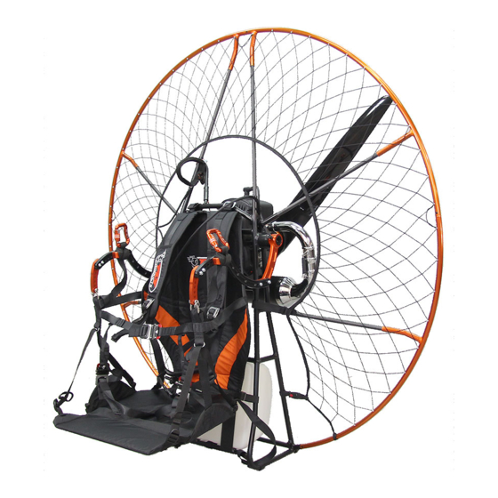
- Page 4 WARNING can result in serious injury or even death. ECLIPSE and RIDER features FLY PRODUCTS presents these very light, but robust, Paramotors whose features are great versatility and ease in disassembly and assembly. Pag. 4...
-
Page 5: Overall Dimensions
ECLIPSE–RIDER USER MANUAL_____________ VER. 1.1 Overall dimensions MODEL (cm/in.) (cm/in.) (cm/in.) ECLIPSE (MAX PROPELLER 130) 142/55.9 142/55.9 Engine ATOM = 45/17.7 RIDER PROPELLER 130 MONO RIM 146/57.5 144/56.7 Engine MOSTER = 42/16.5 RIDER PROPELLER 130 DOUBLE RIM 150/59.0 143/56.3 Engine THOR 202 = 50/19.6 RIDER PROPELLER 140 MONO RIM 153/60.2 153/60.2... -
Page 6: Frame Assembly
ECLIPSE–RIDER USER MANUAL__ _____________ VER. 1.1 FRAME ASSEMBLY The engagement system used "clip button" or snap button, greatly simplifies the assembly procedure. For a correct use, keeping the button pressed, engage the two parts and rotate them slightly until the clicking button comes out of the hole. - Page 7 ECLIPSE–RIDER USER MANUAL_____________ VER. 1.1 To start: Insert the starter support “D” on the central engine frame first. Hook the starting pulley on the starter support as shown in the figure. Insert the LONG (A) rods in the central frame. NOTE : Pay attention to the correct pulley positioning inside the support.
- Page 8 ECLIPSE–RIDER USER MANUAL__ _____________ VER. 1.1 Begin assembling the outer frame circle by following the procedure: Thread the two upper parts of the cage without joining them together, the connection will be made after inserting the remaining parts of the cage. ...
- Page 9 ECLIPSE–RIDER USER MANUAL_____________ VER. 1.1 Once all the insertions of the external frame into the slats have been completed, proceed to the lower RIGHT and LEFT coupling, checking that the sealing button has come out correctly from its hole and the part is actually locked.
- Page 10 ECLIPSE–RIDER USER MANUAL__ _____________ VER. 1.1 Connect the two upper semicircles together, always checking that the sealing button has come out correctly from its hole and that the coupling is actually firm. To complete the assembly of the cage, hook the RIGHT and LEFT side velcro straps as follows: Open the velcro and pass it through the prepared eyelet following the direction indicated.
- Page 11 ECLIPSE–RIDER USER MANUAL_____________ VER. 1.1 Turn the velcro around the loop and Firmly tighten parts to ensure lock it properly in place. complete matching. REPEAT THE SAME OPERATION ON THE OTHER SIDE Finally, join the lower plastic buckles to fix and perfectly stretch the net: Hook the parts making sure the buckle is Lock the coupling by moving the button as perfectly sealed.
-
Page 12: Cage Disassembly
ECLIPSE–RIDER USER MANUAL__ _____________ VER. 1.1 CAGE DISASSEMBLY To disassemble the cage avoiding to force some parts too much and avoid possible damage, we recommend proceeding with the following sequence of operations: Start by unlocking the safety of the lower plastic buckle and unlock it, repeat the same operation on the other side before continuing. - Page 13 ECLIPSE–RIDER USER MANUAL_____________ VER. 1.1 Unlock and release the net from the RIGHT and LEFT side velcro straps, taking care to close the velcros on itself. Uncouple the upper cage from the lower one by pressing the push-pin button and pulling the upper part upwards.
- Page 14 ECLIPSE–RIDER USER MANUAL__ _____________ VER. 1.1 10-11 Unhook the lower cage by pressing the push-pin button and pulling the part outwards. Repeat the operation on the other side 12-13 Slide the lower cage out of the rods while holding them firmly in place. Repeat the operation on the other side Pag.
- Page 15 ECLIPSE–RIDER USER MANUAL_____________ VER. 1.1 14-15 Remove the upper SIDE cage from the rods, holding them firmly in place. Repeat the operation on the other side Join together the two plastic buckles of the disassembled net below. Lift the two lower semicircles to the top with the nets joined by the plastic buckles and hold the four parts at the...
- Page 16 ECLIPSE–RIDER USER MANUAL__ _____________ VER. 1.1 18-19 Remove the last two semicircles from the rods and fold everything in a booklet so that the cage is ready and folded in the correct way to put it back in its bag. This operation ends the disassembly of the cage.
- Page 17 ECLIPSE–RIDER USER MANUAL_____________ VER. 1.1 RIDER SINGLE RIM FRAME The assembly and disassembly operations of the single rim frame of the RIDER series are identical to the ECLIPSE frame, therefore it is advisable to follow the procedure explained above. The only differences are the double upper attachment and the two double lateral attachments.
- Page 18 ECLIPSE–RIDER USER MANUAL__ _____________ VER. 1.1 RIDER DOUBLE RIM FRAME ASSEMBLY AT THE SAME TIME AT THE SAME TIME In order not to force the net excessively, it is recommended follow the illustrated sequence with the parts DETACHED from each other taking care to insert points "4"...
- Page 19 ECLIPSE–RIDER USER MANUAL_____________ VER. 1.1 DOUBLE RIM RIDER FRAME DISASSEMBLY AT THE SAME TIME AT THE SAME TIME For disassembly, after opening all the closing velcro straps, (it is good norm to close them on itself to prevent they stick to the net in the subsequent operations) detach all the joints of the outer rim starting from points –...
- Page 20 ECLIPSE–RIDER USER MANUAL__ _____________ VER. 1.1 MOUNT THE TANK Turn the strap around the tube between the two velcroes, and close them to stop it. Place the tank in the correct position onto its supports and lock it as shown below. Pag.
- Page 21 ECLIPSE–RIDER USER MANUAL_____________ VER. 1.1 Pass the belt inside the red eyelet, close it and lock it with the safety belt (S) as shown in the photo. To release the tank, open the safety little belt (S), detach the velcro from the closure, release the red eyelet and pull it back to help the rings open.
- Page 22 ECLIPSE–RIDER USER MANUAL__ _____________ VER. 1.1 ECLIPSE HARNESS ASSEMBLY AND SETTINGS Fit the harness by hooking it to the central frame using the two upper straps which have TWO different colored indicators to adapt it to the different sizes as shown in the photo: Indicator FOR SIZES Indicator...
- Page 23 ECLIPSE–RIDER USER MANUAL_____________ VER. 1.1 Store the straps away stopping them under the loops as shown in the photo. Hook the middle side straps of the harness having as a reference the red seam as shown in the photo. Hook the lower harness anchoring straps taking care to pass behind the leg of the frame and...
- Page 24 ECLIPSE–RIDER USER MANUAL__ _____________ VER. 1.1 Put the pivot arms in position and, taking care to line the holes, lock them with the push pins keeping the button pressed and releasing it only after it has completely entered. ATTENTION When mount the pivot arms, always be careful that the belt is in...
- Page 25 ECLIPSE–RIDER USER MANUAL_____________ VER. 1.1 To avoid possible entanglement when disassembling the pivot arms, we recommend placing them in the appropriate slots. It is possible to adjust the seat deep by removing or adding the extension blocking it on the prepared velcro. Products ©...
- Page 26 ECLIPSE–RIDER USER MANUAL__ _____________ VER. 1.1 RIDER HARNESS ASSEMBLY AND SETTINGS For a correct use of the push-pin, keep the button pressed while it is slipping and Insert the harness on the prepared while closing the safety catch, plate and lock the push-pin. CHECK THAT IT IS LOCKED! Hook the four lower straps onto the quick-lock provided bucklets.
- Page 27 ECLIPSE–RIDER USER MANUAL_____________ VER. 1.1 Hook the elastic rope of the starter handle to the prepared eyelet and lock it under the velcro for 5-10 cm. (2-4 In.) Put the pivotarms in position and, taking care to keep the holes in axis, block them with the push pins.
- Page 28 ECLIPSE–RIDER USER MANUAL__ _____________ VER. 1.1 It is possible to adjust the depth of the seat blocking it in the desired position on the prepared velcro. OPTIMAL ADJUSTMENTS Adjust the vertical position of the paramotor on the shoulders. Pag.
- Page 29 ECLIPSE–RIDER USER MANUAL_____________ VER. 1.1 Harness height adjustment to facilitate the takeoff run. ADJUSTMENTS TO THE SIMULATOR Adjustments are very important for safety and comfort. Test the position before making the first flight. Hang the paramotor and check the inclination that must be between 25 °...
- Page 30 ECLIPSE–RIDER USER MANUAL__ _____________ VER. 1.1 PIVOT ARMS ADJUSTEMENTS The first rule to be observed is the position of the attachments according to the direction of the fixing screws. The bolt heads are positioned inside and the nuts on the outside of the arms, this to avoid wear of the harness...
- Page 31 ECLIPSE–RIDER USER MANUAL_____________ VER. 1.1 SETTING # PILOT WEIGHT Pilot weight adjustment it is obtained by moving the point of attachment of the paraglider of one or more holes forward for heavy pilots or back for light riders like this scheme: ...
- Page 32 ECLIPSE–RIDER USER MANUAL__ _____________ VER. 1.1 The optimal position of the paramotor in the simulator is between degrees; in flight the trim will compensate for the propeller thrust (depends on the engine power and weights). SETTING # PILOT SIZE Pilot size adjustment is obtained by moving the clutch arm “A”...
- Page 33 ECLIPSE–RIDER USER MANUAL_____________ VER. 1.1 For size (extra small) or to lift the seat you can move backwards the front support "B" with the possibility of raise further the cricket "C" of 1 hole up. SETTING # THE TORQUE A very important setting concerns the contrast to the torque generated by the rotation of the propeller which can be: ◙...
- Page 34 ECLIPSE–RIDER USER MANUAL__ _____________ VER. 1.1 To correctly assemble the paraglider coupling belt, first insert the end "C" in the loop of the belt hooked to the shackle and then pass the entire belt from the "A" side into the loop "C": Pag.
- Page 35 ECLIPSE–RIDER USER MANUAL_____________ VER. 1.1 Tighten the low anchor "C" well, then proceed by inserting the end "A" upwards coming out of the support "D": Products © Copyright s.r.l. Pag.
- Page 36 ECLIPSE–RIDER USER MANUAL__ _____________ VER. 1.1 To finish the assembly, pass the end "A" in the Loop "B", pull hard to free the Loop "A" to which hook the carabiner: This operation performed on both sides, ends assembly of the pivot arms Pag.
- Page 37 ECLIPSE–RIDER USER MANUAL_____________ VER. 1.1 To further increase the anti-torque effect, the “A” belt can be inserted from the external side of the attachment, effectively shifting the paraglider's hooking point: Products © Copyright s.r.l. Pag.
- Page 38 ECLIPSE–RIDER USER MANUAL__ _____________ VER. 1.1 WARNING: Do not over tighten these nuts to avoid weakening the structure and therefore the seal! Preferably use a torque wrench calibrated at N-m (Newton / meter) which correspond to about 1 Kg. (2.2 lb) Pag.
-
Page 39: Propeller Assembly
ECLIPSE–RIDER USER MANUAL_____________ VER. 1.1 PROPELLER ASSEMBLY When preassembling the fiber propeller, be careful not to reverse the direction of the blades! Propeller mounting on motors with BELT reduction (COUNTERCLOCKWISE ROTATION) for the MOSTER engine. Propeller mounting on motors with mechanical reduction (CLOCKWISE ROTATION) for the ATOM... - Page 40 ECLIPSE–RIDER USER MANUAL__ _____________ VER. 1.1 MULTIFUNCTIONAL HANDLE THROTTLE CONTROL LEVER START ENGINE BUTTON *only on electric starter engines with) VELCRO HAND TIGHTENING STOP ENGINE BUTTON Pag. 40...
-
Page 41: Warranty
Fly Products, will repair the product free-of-charge. In no event shall Fly Products be liable to the Purchaser or any other person for any loss or damage whether direct or indirect or consequential or incidental, including without limitation, any damages or claims by third parties caused by defective products or otherwise arising from the incorrect or otherwise improper use of this product. This... - Page 42 ECLIPSE–RIDER USER MANUAL__ _____________ VER. 1.1 NOTE Pag. 42...
- Page 43 ECLIPSE–RIDER USER MANUAL_____________ VER. 1.1 © Copyright by Products s.r.l. Via Perù n. 30 - 63066 GROTTAMMARE (AP) - ITALY tel./fax +39.735.632486 www.flyproducts.com - fly@flyproducts.com Products © Copyright s.r.l. Pag.
Need help?
Do you have a question about the ECLIPSE-RIDER and is the answer not in the manual?
Questions and answers