Table of Contents
Advertisement
Quick Links
Advertisement
Table of Contents

Related Manuals for DIEBOLD NIXDORF DN 490


Summary of Contents for DIEBOLD NIXDORF DN 490
- Page 1 DN Series™ 490 Island Drive-up System Operator Manual 01750337284 C...
- Page 2 This document and the information contained herein are provided AS IS AND WITHOUT WARRANTY. In no event shall Diebold Nixdorf or its suppliers be liable for any special, indirect, or consequential dam- ages of any nature resulting from the use of information in this manual. The information contained in this document is subject to change without notice.
-
Page 3: Table Of Contents
4.1.1 Startup and Shutdown ..................4-2 Accessing the Upper Chassis ....................4-6 4.2.1 Opening the Fascia ..................... 4-6 4.2.2 Closing the Fascia....................4-7 Accessing the Safe ......................4-8 4.3.1 Opening the Safe Door Cover................4-8 Copyright © 2021, Diebold Nixdorf 01750337284 C... - Page 4 Cash Dispenser (CMD-V6C) Upper Unit..............3-13 Figure 3-8 Check Deposit Module ...................3-14 Figure 3-9 Coin Dispenser.......................3-15 Figure 3-10 TP29 Journal Printer ....................3-16 Figure 3-11 TP31R Receipt Printer ...................3-17 Figure 3-12 Air Conditioner and Heater (upper chassis) ............3-18 Copyright © 2021, Diebold Nixdorf 01750337284 C...
- Page 5 Figure 4-22 How to Read Bar Codes..................4-41 Figure 4-23 P-lock Mechanism ....................4-42 Figure 4-24 Upper Unit Release Latch ..................4-43 Figure 4-25 Lockable/Removable Card Box Location ...............4-44 Figure 4-26 Removing the Card Box ..................4-45 Copyright © 2021, Diebold Nixdorf 01750337284 C...
- Page 6 Table B-2 System Conditions ....................B-2 Table B-3 Installation Specifications ..................B-3 Table B-4 Plinth Weights ......................B-3 Table B-5 Effective Power and Heat Output ................B-4 Table B-6 Mechanical Environmental Conditions ..............B-4 Table B-7 Environmental Conditions ..................B-4 Copyright © 2021, Diebold Nixdorf 01750337284 C...
-
Page 7: Introduction
Accessing the upper chassis and safe (Section 4) • Cleaning the exterior of the system (Section 5) • Related documentation (Appendix A ) To perform maintenance on an individual component, refer to the operating guide in Appendix A . Copyright © 2021, Diebold Nixdorf 01750337284 C... -
Page 8: Safety
Operate the system and the components correctly in accordance with this manual in order to avoid injuries and damage to the plant. Keep this manual available and consult it for guidance when you are unsure about how to carry out one or another of the procedures. Copyright © 2021, Diebold Nixdorf 01750337284 C... - Page 9 Interrupting the power connection between the UPS (uninterruptible power supply) and the system (see chapter "Introduction", section "General power interruption" in the operating manual); For further system-specific notes, please refer to the operating manuals. Inform the customer service responsible for you. Copyright © 2021, Diebold Nixdorf 01750337284 C...
- Page 10 Note that there are only safety extra-low voltage circuits (SELV circuits) if you want to feed voltage from an external source into prepared cables to install additional electronics (e. g. EMA connection). • To clean the system only use cleaning agents approved by Diebold Nixdorf (see chapter "Cleaning, Service and Maintenance" in the operating manual). •...
-
Page 11: System Overview
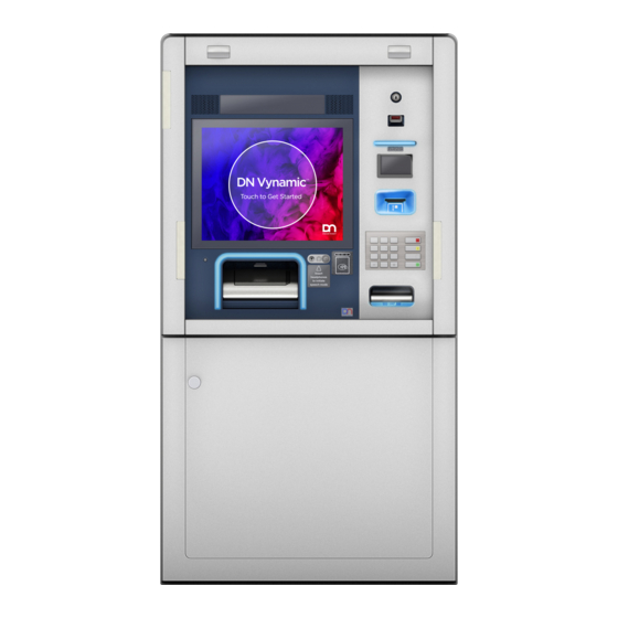
It is designed with a flat fascia so that consumers can drive up to the system, view the options, and perform transactions while remaining in their automobiles. Supplies are replenished and service is performed from the front of the system (see Figure 3-1). Copyright © 2021, Diebold Nixdorf 01750337284 C... -
Page 12: Figure 3-1 Dn Series™ 490 Island Drive-Up System
System Description Figure 3-1: DN Series™ 490 Island Drive-up System Copyright © 2021, Diebold Nixdorf 01750337284 C... -
Page 13: Before Performing Maintenance Procedures On The System
The operator maintenance interface for the system is the consumer display. The operator uses the but- tons on the external control unit with the operator interface to perform routine maintenance procedures. Copyright © 2021, Diebold Nixdorf 01750337284 C... -
Page 14: Maintenance Tasks
Replenishing printer paper, clearing stuck paper, and replacing printer cartridges • Removing cash that is not moving from the recycling module • Removing checks that are not moving from the check deposit module • Removing stuck coins from the coin dispenser Copyright © 2021, Diebold Nixdorf 01750337284 C... -
Page 15: Fascia Components
A typical configuration of the fascia is shown in the figure below. NOTE Your system might not contain all devices described in this section. Some devices are op- tional and some devices cannot be used in combination with other devices (mutually ex- clusive combinations). Copyright © 2021, Diebold Nixdorf 01750337284 C... -
Page 16: Figure 3-2 Modules And Devices Mounted On The Fascia
System Description Figure 3-2: Modules and Devices Mounted on the Fascia Copyright © 2021, Diebold Nixdorf 01750337284 C... - Page 17 Encrypting PIN pad (consumer keypad) Check deposit module slot NFC contactless card reader Coin dispenser slot Headphone jack (and volume control) Cash recycler or cash dispenser slot Safe door cover lock Function keys Consumer display Traffic light Copyright © 2021, Diebold Nixdorf 01750337284 C...
- Page 18 These lights can display in colors and are used by the devices in the figure below. Figure 3-3: User Guide Lights Bar code reader Receipt printer slot Card reader slot Check deposit module slot Coin dispenser slot Cash recycler or cash dispenser slot Copyright © 2021, Diebold Nixdorf 01750337284 C...
-
Page 19: Figure 3-4 Fingerprint Scanner
The motorized card reader has three types of card retain bins. • Locked card retain bin ( refer to Section 4.13) • Lockable and removable card retain box (refer to Section 4.12) • Open bin (refer to Section 4.7) Copyright © 2021, Diebold Nixdorf 01750337284 C... -
Page 20: Upper Chassis Components
NOTE Your system might not contain all devices described in this section. Some devices are op- tional and some devices cannot be used in combination with other devices (mutually ex- clusive combinations). Copyright © 2021, Diebold Nixdorf 3-10 01750337284 C... -
Page 21: Figure 3-5 Upper Chassis Devices
System Description Figure 3-5: Upper Chassis Devices Cash recycler or cash dispenser upper unit (with optional P-lock Coin dispenser Receipt printer External control unit Air conditioner Journal printer Heater (upper chassis) Check depositor module Copyright © 2021, Diebold Nixdorf 3-11 01750337284 C... -
Page 22: Figure 3-6 Recycling Module (Rm4V) Upper Unit
For more information, refer to the DN Series™ Recycling Module (RM4V) Operator Manual (Order Num- ber 01750308109) or DN Series™ Recycling Module (RM4H) Dispenser Operator Manual (Order Num- ber 01750306327). Figure 3-6: Recycling Module (RM4V) Upper Unit Copyright © 2021, Diebold Nixdorf 3-12 01750337284 C... -
Page 23: Figure 3-7 Cash Dispenser (Cmd-V6C) Upper Unit
For more information, refer to the DN Series™ CMD-V6C Cash Dispenser Operating Manual (Order Number 01750342709). Figure 3-7: Cash Dispenser (CMD-V6C) Upper Unit Copyright © 2021, Diebold Nixdorf 3-13 01750337284 C... - Page 24 Checks can be inserted face up or face down with the short edge first for proper orientation. For more information, refer to the DN Series™ Check Deposit Module Operator Manual (Order Number 01750333061). Figure 3-8: Check Deposit Module Copyright © 2021, Diebold Nixdorf 3-14 01750337284 C...
- Page 25 The system may have a coin dispenser that dispenses coins in four different denominations. For more information, refer to the DN Series™ Coin Dispenser Operator Manual (Order Number 01750333943). Figure 3-9: Coin Dispenser Coin dispenser Upper chassis Coin chute Coin slot Safe door cover Copyright © 2021, Diebold Nixdorf 3-15 01750337284 C...
-
Page 26: Figure 3-10 Tp29 Journal Printer
TP29 Journal Printer The TP29 journal printer can process paper rolls which have been coated on their upper side. Refer to the Journal Printer TP29 Operator Manual (Order Number 01750333697). Figure 3-10: TP29 Journal Printer Copyright © 2021, Diebold Nixdorf 3-16 01750337284 C... -
Page 27: Figure 3-11 Tp31R Receipt Printer
The air conditioner is mounted in the upper chassis at the rear of the system. See Figure 3-12. During warm weather, the air conditioner helps maintain the operating temperature in the fascia area of the system. Copyright © 2021, Diebold Nixdorf 3-17 01750337284 C... -
Page 28: Figure 3-12 Air Conditioner And Heater (Upper Chassis)
System Description Figure 3-12: Air Conditioner and Heater (upper chassis) Heater Upper chassis Fascia Air conditioner Copyright © 2021, Diebold Nixdorf 3-18 01750337284 C... - Page 29 Pressing the wrench service button initiates the service (maintenance) mode. Use T/SOP to perform sys- tem and module maintenance procedures. External Control Unit The external control unit controls the power supply to the system devices (see Figure 3-13). Copyright © 2021, Diebold Nixdorf 3-19 01750337284 C...
-
Page 30: External Control Unit
3.3.1 External Control Unit Figure 3-13: External Control Unit - Overview On / Off LED Service button Main voltage LED Service LED Charging status LED (full) On / Off Button Status UPS LED Copyright © 2021, Diebold Nixdorf 3-20 01750337284 C... -
Page 31: Table 3-2 Functions Of The On/Off Button
If the LED is green, the system is operated via the normal mains supply. • If the LED lights up yellow, UPS operation is active. Battery Status Indicator The battery status indicator consists of two LEDs, which can indicate different battery statuses (see Figure 3-13). Copyright © 2021, Diebold Nixdorf 3-21 01750337284 C... - Page 32 Main voltage off, battery charger off or not connected Main voltage switched on, system switched off FLASHING Main voltage switched on, system starts or shuts down Main voltage switched on, system ready for operation System runs in battery mode Copyright © 2021, Diebold Nixdorf 3-22 01750337284 C...
- Page 33 Description T/SOP is active, or emulated switch is in service position. FLASHING T/SOP is active, 36V and/or 25V are switched off T/SOP is inactive and emulated switch is in "in operation" position. Copyright © 2021, Diebold Nixdorf 3-23 01750337284 C...
-
Page 34: Safe Components
NOTE Your system might not contain all devices described in this section. Some devices are op- tional and some devices cannot be used in combination with other devices (mutually ex- clusive combinations). Copyright © 2021, Diebold Nixdorf 3-24 01750337284 C... - Page 35 System Description Figure 3-14: Devices Located in the Safe Cash recycler (RM4V) All-In cassette with multi-purpose bin Safe lock (boltwork) Heater Cash recycler (RM4V) lower unit Cash recycler (RM4V) recycling cassettes Copyright © 2021, Diebold Nixdorf 3-25 01750337284 C...
- Page 36 System Description Figure 3-15: More Devices Located in the Safe Cash dispenser (CMD-V6C) reject/retract cassette Cash dispenser (CMD-V6C) supply cassettes Cash dispenser (CMD-V6C) lower unit Copyright © 2021, Diebold Nixdorf 3-26 01750337284 C...
- Page 37 System Description Figure 3-16: Devices Located in the Safe (RM4H) Safe Recycling module lower unit (horizontal) Recycling module recycling cassettes Copyright © 2021, Diebold Nixdorf 3-27 01750337284 C...
-
Page 38: Cash Recycler (Rm4V) Lower Unit
All-In cassette. Refer to the Recycling Module (RM4V) Dispenser Operator Manual (Order Number 01750308109). Figure 3-17: Cash Recycler (RM4V) Lower Unit Copyright © 2021, Diebold Nixdorf 3-28 01750337284 C... -
Page 39: Cash Recycler (Rm4V) Recycling Cassettes
Figure 3-19). The secure cassette can use security seals to indicate tampering. The cassettes can be re- moved and reinserted into the cash recycler lower unit multiple times (i.e., "multiple-insertion") without having to reset a security feature. Figure 3-18: Convenience Recycling Cassette Lever Recycling convenience cassette Copyright © 2021, Diebold Nixdorf 3-29 01750337284 C... - Page 40 System Description Figure 3-19: Secure Recycling Cassette Secure recycling cassette Lock Copyright © 2021, Diebold Nixdorf 3-30 01750337284 C...
-
Page 41: Cash Recycler (Rm4V) All-In Cassette
All-In cassette. Figure 3-20: RM4V All-In Cassette (Secure Cassette Shown) All-In cassette Multipurpose/Retract bin lock (on the back of the cassette) Primary compartment lock Copyright © 2021, Diebold Nixdorf 3-31 01750337284 C... -
Page 42: Cash Recycler (Rm4V) Cassette Physical Description
If the media is too mutilated or wrin- kled, or if multiple notes are picked at the same time, the notes go to the reject/retract cassette instead of being delivered to the consumer. Copyright © 2021, Diebold Nixdorf 3-32 01750337284 C... - Page 43 System Description For more information, refer to the DN Series™ CMD-V6C Cash Dispenser Operating Manual (Order Number 01750342709). Figure 3-21: CMD-V6C Lower Unit Copyright © 2021, Diebold Nixdorf 3-33 01750337284 C...
-
Page 44: Cash Dispenser (Cmd-V6C) Supply Cassettes
The front door of the supply cassette opens with a simple lever and can be pushed shut to close. The cassette can be removed and reinserted into the CMD-V6C multiple times without having to reset a se- curity feature. Figure 3-22: CMD-V6C Supply Cassette Copyright © 2021, Diebold Nixdorf 3-34 01750337284 C... -
Page 45: Cash Dispenser (Cmd-V6C) Reject/Retract Cassette
Cash Dispenser (CMD-V6C) Reject/Retract Cassette Notes that are stored in the reject/retract cassette were recognized as counterfeit money, damaged, or were not removed by the customer during the cash-out procedure. Figure 3-23: CMD-V6C Reject/Retract Cassette Copyright © 2021, Diebold Nixdorf 3-35 01750337284 C... -
Page 46: Cash Dispenser (Cmd-V6C) Cassette Physical Description
420 mm total capacity approximately 3500 notes Table 3-11: Media Capacity of the Retract/Reject Cassette Size of media stack 110 notes for retract notes Capacity (new 20 Euro) 400 notes for reject notes Copyright © 2021, Diebold Nixdorf 3-36 01750337284 C... -
Page 47: Recycling Module Rm4H, Overview
Banknotes which can not be clearly identified as well as banknotes forgotten or not removed by the customer in a withdrawal, are placed in the reject/retract cassette or in the All In Box (configuration- dependent). • The input/output tray is protected by a shutter on the system side. Copyright © 2021, Diebold Nixdorf 3-37 01750337284 C... - Page 48 System Description Figure 3-24: RM4H Lower Unit All in Box Distributor module Safe compartment 4 through Recycling cassettes Copyright © 2021, Diebold Nixdorf 3-38 01750337284 C...
-
Page 49: Recycling Module Rm4H, Standard Cassette
The standard cassette is available in a basic, mid-range or high end configuration. Figure 3-25: Standard Cassette Basic/Midrange Cover LED display - Status display (midrange only) Location for rating/cassette label Handle Release lever Lock (optional) Copyright © 2021, Diebold Nixdorf 3-39 01750337284 C... -
Page 50: Recycling Module Rm4H, All-In Cassette
The All-in Cassette can be a secure or convenience cassette. The primary compartment latches or un- locks like the recycling cassettes. Figure 3-26: All-in Cassette Cover Location for rating /cassette label Handle Release lever of lock Lead seal possibility Copyright © 2021, Diebold Nixdorf 3-40 01750337284 C... -
Page 51: Recycling Module Rm4H, Cassette Physical Description
The weight of a completely filled cassette was ascertained using banknotes with a denomination of 50 euros. Refers to brand new banknotes Copyright © 2021, Diebold Nixdorf 3-41 01750337284 C... - Page 52 The weight of a completely filled cassette was ascertained using banknotes with a denomination of 50 euros. Refers to brand new banknotes Copyright © 2021, Diebold Nixdorf 3-42 01750337284 C...
- Page 53 The storage capacity and weight of a completely filled cassette depends on the type, quality, nature and state of the banknotes. The weight of a completely filled cassette was ascertained using banknotes with a denomina- tion of 50 euros. refers to brand new banknotes Copyright © 2021, Diebold Nixdorf 3-43 01750337284 C...
-
Page 54: Heater (Safe)
The heat thermostat, integral to the basic alarms panel, senses when the temperature inside the system safe exceeds a certain level. If this level is exceeded, the heat thermostat initiates an alarm. Copyright © 2021, Diebold Nixdorf 3-44 01750337284 C... -
Page 55: Options
Follow the instructions displayed on the monitor. If an er- ror occurs inform your service representative. Yellow - Supplies Required Follow the instructions displayed on the monitor. Green - In Service Device is in operation Copyright © 2021, Diebold Nixdorf 3-45 01750337284 C... - Page 56 If there are banknotes in the upper unit, the upper unit is locked in place until the safe door is opened and the P-lock is released, then the upper unit can slide out of the upper chassis. Refer to Section 4.11 to access the P-lock. Copyright © 2021, Diebold Nixdorf 3-46 01750337284 C...
- Page 57 To avoid risk of death, severe personal injury, or equipment damage, always follow the written maintenance procedures for the system and its individual modules. NOTE For maintenance procedures for the individual system modules, refer to the module oper- ating guides listed in Appendix A . Copyright © 2021, Diebold Nixdorf 01750337284 C...
-
Page 58: T/Sop
ü Make sure the power switch is on. Press the on/off button on the external con- trol unit (see chapter External control unit Overview). The ON/OFF LED lights up green. The system starts. Figure 4-1: Switching off the System Copyright © 2021, Diebold Nixdorf 01750337284 C... - Page 59 Notice that modules that share the same power rail will also be powered off and on. Also refer to the Technical Service and Operating (T/SOP) for ProBase/C and ProBase/J User Manual for more information. Copyright © 2021, Diebold Nixdorf 01750337284 C...
- Page 60 To power down specific modules, press the wrench button on the external control unit (Figure 3-13). Refer to the T/SOP Device Overview screen to power down specific power rails (Figure 4-3). Refer to T/SOP to power down specific modules (Figure 4-4). Copyright © 2021, Diebold Nixdorf 01750337284 C...
- Page 61 Operation Figure 4-4: T/SOP Power Down Specific Modules Screen Copyright © 2021, Diebold Nixdorf 01750337284 C...
-
Page 62: Accessing The Upper Chassis
Refer to the appropriate operating manual listed in Appendix A for information on completing the maintenance procedures for your system's modules. Figure 4-5: Opening the Fascia System Fascia in open position Key for the fascia lock (turn key clockwise) Copyright © 2021, Diebold Nixdorf 01750337284 C... -
Page 63: Closing The Fascia
Tug gently on the fascia after it is closed to make sure it is properly locked. Figure 4-6: Closing the Fascia System Fascia in the open position Fascia key slot (key not present) Copyright © 2021, Diebold Nixdorf 01750337284 C... -
Page 64: Accessing The Safe
Refer to the appropriate section in this manual to access the desired component. Refer to the appropriate operating manual listed in Appendix A for information on completing the maintenance procedures for your system's modules. Copyright © 2021, Diebold Nixdorf 01750337284 C... - Page 65 Operation Figure 4-7: Opening the Safe Door Cover System Rotate the key counterclockwise Lock assembly Safe door cover Safe door Copyright © 2021, Diebold Nixdorf 01750337284 C...
-
Page 66: Opening/Closing The Safe Door
The key-operated lock must then be set to the original key. It is not allowed to use the standard key several times or even permanently. Standard key This key is used to open the safe door with the factory-preset number combination lock. Copyright © 2021, Diebold Nixdorf 4-10 01750337284 C... - Page 67 Do not count the number of turns but the number of times the numbers appear below the opening index. The number combination lock is preset at the factory. Copyright © 2021, Diebold Nixdorf 4-11 01750337284 C...
- Page 68 '50' positioned exactly below the opening index. Then turn the dial of the number combination lock clockwise as far as possible. This releases the number combination lock. Open the key-operated lock cap (if installed). Copyright © 2021, Diebold Nixdorf 4-12 01750337284 C...
- Page 69 Insert the standard key into the lock. Turn the key clockwise as far as possible. Turn the locking/unlocking lever or wheel counterclockwise as far as possible. 10. Open the safe door as far as possible. Copyright © 2021, Diebold Nixdorf 4-13 01750337284 C...
- Page 70 Close the cap of the lock (if installed). NOTE To change the number combination, you must turn the dial at least one full turn to the left and then four full turns to the right. Copyright © 2021, Diebold Nixdorf 4-14 01750337284 C...
- Page 71 Close the system (see section "Opening/closing the system doors") Close the front door or the standard/design door depending on the system used (refer to the sys- tem-specific operating manual, chapter "Basic operation"). Copyright © 2021, Diebold Nixdorf 4-15 01750337284 C...
- Page 72 - Always keep your keys in a safe place. - If you lose or misplace a key, always change the lock to fit a new key immediately, even if the original key (the previous key) is recovered. Copyright © 2021, Diebold Nixdorf 4-16 01750337284 C...
- Page 73 Remove the key. The lock is now set to the new key. NOTE Before you close the door, check at least three times that the lock works correctly with the new key. Copyright © 2021, Diebold Nixdorf 4-17 01750337284 C...
- Page 74 The position of the service opening on the inside of the safe door depends on the safe type used. The illustration shows possible positions (1) or (2) of the service opening for the reset key. Copyright © 2021, Diebold Nixdorf 4-18 01750337284 C...
- Page 75 Test the new combination on the opening index at least 3 times with the safe door open. The new code is now set. NOTE Test the new combination on the opening index at least 3 times with the safe door open. Copyright © 2021, Diebold Nixdorf 4-19 01750337284 C...
- Page 76 The system comes with three original keys, which are used to open and close the safe door after instal- lation: 3 Original keys: These keys are used to open the safe door after system installation. Copyright © 2021, Diebold Nixdorf 4-20 01750337284 C...
- Page 77 Turn the dial counterclockwise until the first number appears exactly below the opening index for the fourth time. Copyright © 2021, Diebold Nixdorf 4-21 01750337284 C...
- Page 78 Turn the dial counterclockwise until the third number appears exactly below the opening index for the second time. Then turn the dial clockwise as far as possi- ble. This releases the number combination lock. Copyright © 2021, Diebold Nixdorf 4-22 01750337284 C...
- Page 79 Operation Open the key-operated lock cap (if installed). Insert the original key into the lock. 10. Turn the key clockwise as far as possible. Copyright © 2021, Diebold Nixdorf 4-23 01750337284 C...
- Page 80 Operation 11. Turn the locking/unlocking lever or wheel counterclockwise as far as possible. 12. Open the safe door as far as possible. Copyright © 2021, Diebold Nixdorf 4-24 01750337284 C...
- Page 81 Close the cap of the lock (if installed). NOTE To change the number combination, you must turn the dial at least one full turn to the left and then four full turns to the right. Copyright © 2021, Diebold Nixdorf 4-25 01750337284 C...
- Page 82 Close the front door or the standard/design door depending on the system used (refer to the sys- tem-specific operating manual, chapter "Basic operation"). Copyright © 2021, Diebold Nixdorf 4-26 01750337284 C...
-
Page 83: Closing The Safe Door Cover
Tug gently on the safe door cover to make sure it is properly locked. Figure 4-8: Closing the Safe Door Cover System Rotate the key clockwise Lock assembly Safe door cover Safe door Copyright © 2021, Diebold Nixdorf 4-27 01750337284 C... -
Page 84: System And Device Touch Points
Coin dispenser tray release latch (pull pin) Coin dispenser tray handle Cash dispenser (CMD-V6C) or cash recycler (RM4V) upper unit release latch System Cash dispenser (CMD-V6C) or cash recycler (RM4V) upper unit handle Fascia not shown for clarity. Copyright © 2021, Diebold Nixdorf 4-28 01750337284 C... - Page 85 Operation Figure 4-10: More Upper Chassis Touch Points System Printer tray handle Check deposit module handle Fascia not shown for clarity. Copyright © 2021, Diebold Nixdorf 4-29 01750337284 C...
- Page 86 Operation Figure 4-11: Safe Touch Points Recycling module (RM4V) cassettes Loopback transport release latch Recycling module (RM4V) lower unit release latch Recycling module (RM4V) lower unit handle Chest horizontal transport handle Copyright © 2021, Diebold Nixdorf 4-30 01750337284 C...
- Page 87 Operation Figure 4-12: More Safe Touch Points Reject/retract cassette handle Head transport release lever Supply cassette handles Supply cassette release latches Cash dispenser (CMD-V6C) release latch Copyright © 2021, Diebold Nixdorf 4-31 01750337284 C...
- Page 88 RM4H Recycling module cassettes RM4H Recycling module cassette handle RM4H Recycling module cassette lid release latch RM4H Recycling module cassette release latch (press down an inch back from the end of the lever) Copyright © 2021, Diebold Nixdorf 4-32 01750337284 C...
-
Page 89: Accessing The Receipt / Journal Printer
Perform specific maintenance procedures on the printer. Refer to the module operating manuals listed in Appendix A for specific maintenance procedures for this module. Push the printer tray completely into the upper chassis. Close and lock the fascia (refer to Section 4.2.2). Copyright © 2021, Diebold Nixdorf 4-33 01750337284 C... - Page 90 Operation Figure 4-14: Accessing the Receipt / Journal Printer System (upper chassis) Receipt printer Printer tray handle Fascia not shown for clarity. Copyright © 2021, Diebold Nixdorf 4-34 01750337284 C...
-
Page 91: Accessing The Check Deposit Module
Close and lock the fascia (refer to Section 4.2.2). Figure 4-15: Accessing the Check Deposit Module Upper chassis Check deposit module tray handle Direction to pull out check deposit module Check deposit module Fascia not shown for clarity. Copyright © 2021, Diebold Nixdorf 4-35 01750337284 C... -
Page 92: Accessing The Open Card Retain Bin And The Card Reader
Close the fascia (refer to Section 4.2.2). Figure 4-16: Accessing the Open Card Retain Bin and Card Reader Fascia Card reader mounting tray Open card retain bin Card reader Copyright © 2021, Diebold Nixdorf 4-36 01750337284 C... -
Page 93: Accessing The Coin Dispenser
Close and lock the fascia (refer to Section 4.2.2). Figure 4-17: Accessing the Coin Dispenser Coin dispenser tray release latch (pull pin) Coin dispenser Upper chassis Coin dispenser tray handle Fascia not shown for clarity. Copyright © 2021, Diebold Nixdorf 4-37 01750337284 C... -
Page 94: Pulling Out / Pushing In Cash Components
Pulling out / Pushing in the Upper Unit Unlock the upper unit by the release lever (1). Pull the upper unit out of the system by using the release lever (2). Figure 4-18: Pulling out the Upper Unit Copyright © 2021, Diebold Nixdorf 4-38 01750337284 C... -
Page 95: Pulling Out / Pushing In The Lower Unit
The release lever is marked green. Pull the release lever upwards (1). Pull the lower unit out of the system by using the release lever (2). Figure 4-20: Pulling out the Lower Unit Copyright © 2021, Diebold Nixdorf 4-39 01750337284 C... - Page 96 Operation Push the lower unit (1) into the system by using the release lever (2). Figure 4-21: Pushing in the Lower Unit Copyright © 2021, Diebold Nixdorf 4-40 01750337284 C...
-
Page 97: How To Read Bar Codes
Place the scanner light at the center of the bar code and wait for the scanner to pick up the data. You may have to move the scanner light up and down the bar code to get a reading. Figure 4-22: How to Read Bar Codes Bar code scanner Light Bar code Copyright © 2021, Diebold Nixdorf 4-41 01750337284 C... -
Page 98: Accessing The P-Lock
P-lock mechanism Safe The P-lock latching mechanism is open. Pull up on the upper unit release latch (Figure 4-24). Use the upper unit handle to pull the upper unit forward as far as possible. Copyright © 2021, Diebold Nixdorf 4-42 01750337284 C... -
Page 99: Accessing The Lockable/Removable Card Box
Unlock and extend the fascia on its slide assemblies. The card reader and card box are mounted to the back of the fascia (Figure 4-25). Slide the card box away from the fascia (Figure 4-26). Copyright © 2021, Diebold Nixdorf 4-43 01750337284 C... - Page 100 Operation Figure 4-25: Lockable/Removable Card Box Location Lockable/removable card box Card reader tray Card box mounting bracket Copyright © 2021, Diebold Nixdorf 4-44 01750337284 C...
- Page 101 Close and lock the card box cover. The card box resets and the teeth in the card box slot retract. Reinstall the lockable/removable card box (Figure 4-27) onto the mounting bracket. Make sure the lock box audibly locks in place. Copyright © 2021, Diebold Nixdorf 4-45 01750337284 C...
-
Page 102: Accessing The Card Reader Lockable Card Retain Bin
Open bin (Section 4.7) Unlock and open the fascia. The card reader and the lockable retain bin are mounted to the back of the fascia. Unlock and open the lockable retain bin (Figure 4-28). Copyright © 2021, Diebold Nixdorf 4-46 01750337284 C... - Page 103 Operation Figure 4-28: Open the Lockable Card Retain Bin Card bin lock Copyright © 2021, Diebold Nixdorf 4-47 01750337284 C...
-
Page 104: Maintenance
Commercial glass cleaners can be used (with a lint free cloth) on the consumer display (vandal shield or touch screen), if necessary. Cleaning the Keyboards Clean the keyboard surface with a soft cloth lightly moistened with a liquid non-abrasive detergent. Copyright © 2021, Diebold Nixdorf 01750337284 C... -
Page 105: A Related Documentation
DN Series™ TP29 Journal Printer Operator Manual 01750333697 DN Series™ TP31R (with retract) Receipt Printer Operator Manual 01750333705 DN Series™ CMD-V6C Cash Dispenser Operator Manual 01750342709 DN Series™ Recycling Module (RM4H) Dispenser Operator Manual 01750306327 Copyright © 2021, Diebold Nixdorf 01750337284 C... -
Page 106: B Technical Data
Supply voltage range 100-127 V / 200-240 V Rated frequency 50/60 Hz Network type TN (network with PE conductor) Permissible tolerance for rated voltage +/- 10% Permissible tolerance for rated frequency +/- 1% Copyright © 2021, Diebold Nixdorf 01750337284 C... -
Page 107: System Conditions
IP X0 IP X0 tion according to EN 60529: [1] One heater would add 700W. Two heaters (upper chassis and safe) would add 1400W. [2] Air conditioner adds 690W. [3] Air conditioner adds 670W. Copyright © 2021, Diebold Nixdorf 01750337284 C... -
Page 108: Installation Specifications
DN OFA Sockel UL 120mm 36.5 Kg 1750343032 DN OFA Sockel UL 191mm 49Kg 01750340241 DN OFA adj. plinth 155 – 240mm 73 Kg 01750341166 DN OFA adj. plinth 115 – 160mm 65 Kg Copyright © 2021, Diebold Nixdorf 01750337284 C... -
Page 109: Effective Power And Heat Output
Climatic Environmental Condi- tions Air Temperature degree C ( de- Relative Air Humidity (%) gree F) Operation -40C to 50C (-40F to 122F) 5 to 85 (Inside) 0C to 40C (32 F to 104F ) Copyright © 2021, Diebold Nixdorf 01750337284 C... - Page 110 5 to 98 Noise Emissions Characteristic noise value ac- 45 dB(A) Idle mode 55 dB(A) Operation (typical oper- cording to ISO 9296 ating cycle) Workplace-related sound pres- LpAm (at adjacent workplace) sure level Copyright © 2021, Diebold Nixdorf 01750337284 C...
-
Page 111: Compliance With Standards And Approvals
Voltage Directive 2014/35/EU. Certification for Data Transmission The certification number or CE mark of the data transmission module (if available) is attached directly to the DT card or to the housing of the system unit. Copyright © 2021, Diebold Nixdorf 01750337284 C... -
Page 112: Environmental Protection
Please observe the respective national regulations with regard to the disposal of elec- trical equipment. Electrical equipment should not be disposed of as normal municipal waste within the EU (crossed-out wheeled bin symbol). For information regarding the possible repurchase of used systems, please contact: contact.remarketing@dieboldnixdorf.com Copyright © 2021, Diebold Nixdorf 01750337284 C... - Page 113 Refers to a person who performs routine play in colors. maintenance, such as replenishing supplies. An operator may also perform procedures that help determine the cause of certain prob- lems, such as jammed paper in the printer. Copyright © 2021, Diebold Nixdorf viii 01750337284 C...
- Page 114 DIEBOLD NIXDORF 5995 Mayfair Road | North Canton, OH 44720 | United States © 2021 Diebold Nixdorf, Incorporated. All Rights Reserved.
Need help?
Do you have a question about the DN 490 and is the answer not in the manual?
Questions and answers
What are the electrical requirements for this unit 30 amp 110 or 220 needed