Table of Contents
Advertisement
Quick Links
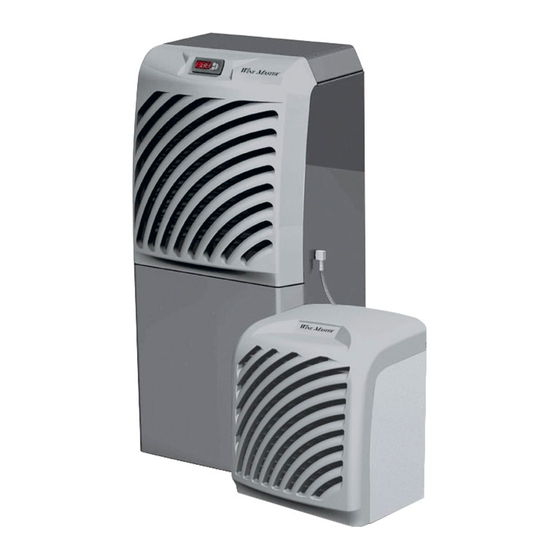
INSTALLATION GUIDE USER GUIDE
WineSP100-8/WineSP100PRO
INDICATIONS PLACED ON THE NAMEPLATE FOUND ON THE APPLIANCE
Model :
Serial number :
Purchase date :
* IMPORTANT: IT IS RECOMMENDED TO NOTE THE
SERIAL NUMBER AND TO WRITE IT DOWN IN THE BOX
ABOVE. IT WILL BE NECESSARY FOR ORDERING
SPARE PARTS
Please
keep
WineSP100/
Réf :
11/2020
Advertisement
Table of Contents

Related Manuals for WINEMASTER WineSP100


Summary of Contents for WINEMASTER WineSP100
- Page 1 INSTALLATION GUIDE USER GUIDE Please keep WineSP100/ WineSP100-8/WineSP100PRO INDICATIONS PLACED ON THE NAMEPLATE FOUND ON THE APPLIANCE Model : Serial number : Purchase date : * IMPORTANT: IT IS RECOMMENDED TO NOTE THE SERIAL NUMBER AND TO WRITE IT DOWN IN THE BOX ABOVE.
-
Page 2: Table Of Contents
THE FIXING BRACKETS ......................16 REFRIGERATION CONNECTION ON INSIDE UNIT ............17 REFRIGERATION CONNECTION ON OUTSIDE UNITS ............17 LOADING ........................... 18 USING THE WINEMASTER SP100 ..................18 CONNECTING THE AIR-CONDITIONER ................18 CONTROL PANEL ........................18 STANDBY MODE ........................19 AUTOMATIC DEFROST ...................... - Page 3 WARRANTY .......................... 22 YEARS CONTRACTUAL WARRANTY .................. 22 TERMS OF APPLICATION OF THE GUARANTEE ..............22 EXCLUSIONS AND LIMITS OF GUARANTEE ..............22...
- Page 4 From conception to commercialisation, everything has been implemented to offer an exclusive and high quality product. Brainchild of a team who find in this a motivation to ever give satisfy you, we hope that your wine conditioning unit WINEMASTER ®...
-
Page 5: Dimensions
CHARACTERISTICS 45 kg (interior) – 15 kg (outside) Weight 1005 mm x 395 mm x 480 (int) 465 mm 360 mm 480mm Dimensions (ext) Setting the temperature Preset to 12°C, adjustable between 8 and 18°C* température Maximum outdoor temperature 35°C** Cooling power 2500W at 12°C** Heating power... -
Page 6: Layout Of Premises
1.3.1 INSULATION Insulation of the 4 walls, the door, the ceiling and the floor is essential for the Winemaster to work properly. Adequate insulation helps to obtain the stability of the temperature and the humidity. The board on the next page ( choice of insulation ) can be used to determine the type and the thickness of insulation needed according to the internal volume of the cellar and a cellar temperature of 12°C. -
Page 7: Choice Of Insulation
1.3.2 CHOICE OF INSULATION MINIMUM THICKNESS OF INSULATION (mm)for 12°C cellar temperature POLYURETHANE CELLAR EXPANDED POLYSTYRENE EXTRUDED POLYSTYRENE FOAM λ=0,025 W/m°C λ=0,044 W/m°C λ=0,030 W/m°C VOLUME (m3) 1.3.3 WALL AND CEILING INSULATION The manufacturers propose their insulation panels in several forms : - insulation alone "complexes"... -
Page 8: The Door
Insert a seal such a foam, between the door panel and the frame all around the edge. Use a WINEMASTER isothermal door, lined with polyurethane foam. It includes a seal around its periphery, with a magnetic closure.. -
Page 9: Flexible Dismounting
FLEXIBLE DISMOUNTING 2.3.1 THE COVER • Unscrew the two black platic screws 1. • Open the cover like shown on the picture 2. -
Page 10: The Fixing Brackets
2.3.2 THE FIXING BRACKETS Unscrew the 5 screws 1 with a screwdriver PZ2 for unmounting the brackets 2 et 3. 2.3.3 THE REFRIGERANT CONNECTION Two wrenches 1 & 2 are supplied with the unit. Maintain the connection with the wrenche 1and unscre with the wrenche 2. -
Page 11: Electrical Connector
Attention : don’t stop unscrewing while gas leaks until the 2 elements are separated.The gas leak will stop then ! Before and during remounting operations, protect the end of the flexible connection in order to avoid dust goes out. 2.3.4 ELECTRICAL CONNECTOR The ventilator of the outside unit is connected by an electric cable. - Page 12 • Position the outside unit so that the screws and washers 1 are engaged in the slot 2 • To finish, screw the kit screws and washer 1 under the unit.
-
Page 13: Installation Of The Inside Unit
INSTALLATION OF THE INSIDE UNIT Put the unit on the floor or on his horizontal support, It shouldn’t be any obstacle in front of the ventilation grid to facilitate the air flow The support or floor must be level and not transmit vibrations. RE-CONNECTION OF THE FLEXIBLE Pass the connecting flexible through the hole in the wall and re-connect the refrigerant fittings with the wrenches and the electrical connecting wires to the outside unit. -
Page 14: Flexible Connection For The 4 And 8M Version
FLEXIBLE CONNECTION FOR THE 4 AND 8M VERSION THE COVER • Unscrew the two black plastic screws 1 • Lift cover 2 by rotating it as shown in the drawing. THE FIXING BRACKETS • Unscrew the 5 screws 1 using a screwdriver PZ2 to release the retaining flanges 2 and 3. -
Page 15: Flexibles Intallation On Outside Unit
FLEXIBLES INTALLATION ON OUTSIDE UNIT BLUE • Put the hoses in place • BE CAREFUL TO RESPECT THE COLOR CODE ON YOUR MACHINE (blue linked to r blue, red linked to red) (2) CONNECTION AND INSTALLATION OF THE PRO VERSION FLEXIBLES The connections must be made of copper for refrigeration use of diameter 3/8’’... -
Page 16: The Cover
THE COVER • Unscrew the two black plastic screws 1 • Lift cover 2 by rotating it as shown in the drawing. THE FIXING BRACKETS • Unscrew the 5 screws 1 using a screwdriver PZ2 to release the retaining flanges 2 and 3. -
Page 17: Refrigeration Connection On Inside Unit
REFRIGERATION CONNECTION ON INSIDE UNIT BLUE • Solder the copper connections to the fittings. CAUTION RESPECT THE COLOR CODE ON YOUR MACHINE (blue linked to blue, red linked to red) REFRIGERATION CONNECTION ON OUTSIDE UNITS BLUE... -
Page 18: Loading
The vacuum draw and the filling are done on the indoor unit. Emptying and filling USING THE WINEMASTER SP100 The Winemaster SP100 must be installed by complying with the national rules of electric installation CONNECTING THE AIR-CONDITIONER Connect the male plug to a 230/16A power socket. Switch on the air-conditioner by pressing the green button on the back of the inside unit.. -
Page 19: Standby Mode
- Press button one second until the targeted temperature is blinking. - Use button to increase the temperature - Use button to lower the temperature. - When the right temperature is set, press again on button confirm it. Explanations of the main display symbols: Red light = cold mode engaged (compressor working) Red light... -
Page 20: 6.5 Manual Defrost
The program of the thermostat from model WINEMASTER SP100 will run an automatic defrost time several times a day. During this position, the compressor stops and only the fan in the cellar is functionning. The condensate water produced during this period will b evacuated through the tube. -
Page 21: Changing The Filter
Remove the cover 2. • Pull the tab 3 to release the filter Replace it with a WINEMASTER filter only ! You can then replace the cover INFORMATION ABOUT AIRCONDITIONNER FUNCTIONNING This airconditionner has a pressostat of high pressure security with manual rearmament and a pressostat of low pressure security with automatic rearmament. - Page 22 In the event of cooling system breackdown, WINEMASTER can ask for the part to be returned for repair following the intervention of a qualified representative. The equipment will be packed and held available for the WINEMASTER carrier to collect it.
Need help?
Do you have a question about the WineSP100 and is the answer not in the manual?
Questions and answers