Table of Contents
Advertisement
Quick Links
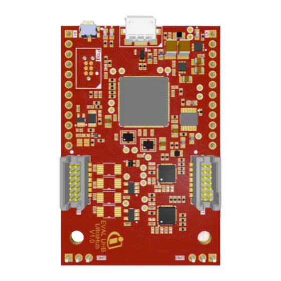
Infineon UltraHub
User manual
About this document
Scope and purpose
This user manual provides information about using and evaluating the Infineon analog and digital XENSIV™
MEMS ultrasonic transceivers with the help of the UltraHub evaluation kit. This user manual familiarizes you
with the UltraHub evaluation board and guides you through the initial hardware and software setup and
measurements. Detailed information about access to serial interface and protocol definitions are included.
Intended audience
Design, verification, test and software engineers can use this document to gain an understanding of the
functionality and connections of the UltraHub evaluation kit.
www.infineon.com
page 1 of 24
Advertisement
Table of Contents

Related Manuals for Infineon UltraHub


Summary of Contents for Infineon UltraHub
-
Page 1: About This Document
This user manual provides information about using and evaluating the Infineon analog and digital XENSIV™ MEMS ultrasonic transceivers with the help of the UltraHub evaluation kit. This user manual familiarizes you with the UltraHub evaluation board and guides you through the initial hardware and software setup and measurements. -
Page 2: Table Of Contents
Infineon UltraHub User manual Table of contents About this document ........................1 Table of contents ..........................2 Introduction .......................... 3 Prerequisites ............................3 1.1.1 Hardware ............................3 1.1.2 Software ............................. 3 Features ..........................4 Summary of features ..........................4 Block diagram ............................4 Initial setup .............................. -
Page 3: Introduction
This document serves as a manual for evaluating up to four Infineon XENSIV™ MEMS ultrasonic transceivers using the UltraHub evaluation kit. The evaluation board provides an USB audio interface to stream audio data from ultrasonic transceivers with audio recording and editing software. Prerequisites 1.1.1... -
Page 4: Features
XENSIV™ MEMS-based ultrasonic transceivers. It consists of two parts: • UltraHub motherboard with microcontroller and audio codec • UltraHub sensing shield, i.e., shields with up to four ultrasonic transceivers (digital or analog) VMIC P_MIC1 N_MIC1 ACT_MIC1 Precision DAC / Precision DAC /... -
Page 5: Initial Setup
Figure 5 shows how the UltraHub sensing shield connects to the MCU baseboard. The mechanical connectors have markers X1 and X2, which should coincide with the same marking on the shield (see Figure 4). The UltraHub sensing shield is equipped with four LEDs, which turn on based on the actuation of the corresponding transceiver. -
Page 6: Evaluation Board Connectors
Infineon UltraHub User manual Indication markers and board-to-board connection of motherboard and sensing shield Figure 4 Evaluation board connectors The UltraHub evaluation board offers a wide variety of connectors, listed in Table 1. Table 1 Connector list Reference designator Description... - Page 7 Infineon UltraHub User manual Schematic (a) and pad layout (b) of the connectors for the sensing shield Figure 5 Schematic (a) and pad layout (b) of the motherboard side pins Figure 6 www.infineon.com page 7 of 24 10/08/2021...
-
Page 8: Host Computer Setup
In the pop-up window of “Performance Options”, go to the “Advanced” tab, select “Background services” and apply changes. Host computer system settings Figure 7 To enable the UltraHub to be opened in exclusive mode: • Open “Windows Sounds Settings”. •... -
Page 9: Audacity Software Setup
Infineon UltraHub User manual Exclusive Mode for UltraHub Figure 8 Audacity software setup Audacity is a free and open-source audio editor and recording application. Select the audio source as “Microphone Array (UltraHubX)” in the recording software, as shown in Figure 9. Select “Windows WASAPI” as the audio driver and “4”... - Page 10 Infineon UltraHub User manual Recording from UltraHub in Audacity Figure 9 www.infineon.com page 10 of 24 10/08/2021...
-
Page 11: Ultrasonic Transmission Configuration
Infineon UltraHub User manual Ultrasonic transmission configuration Enabling ultrasonic transmission The four channels on the sensing shields all record audio signals continuously. The ultrasonic transmitting functionality can instead be configured depending on which of the four channels is required to transmit the ultrasonic bursts according to the pulse-echo principle. -
Page 12: Actuation Modes
Infineon UltraHub User manual Examples of transmitting bursts varying start, end frequency and number of pulses Figure 11 Representation of the PRT and actuation bursts Figure 12 Note: While the PRT can be directly set by the user, the duration of the actuation burst can vary depending on start, end frequencies and number of pulses. - Page 13 Infineon UltraHub User manual Comparison of parallel (A) and cyclic (B) actuation modes, two transceivers active Figure 13 Comparison of parallel (A) and cyclic (B) actuation modes, four transceivers active Figure 14 Note: The cyclic actuation is performed only on the transceivers selected as active. If only one transceiver is selected as active, no difference will be perceived between the two modes.
-
Page 14: Serial Interface
CDC end points. This allows for sending bytes to the serial interface using any serial terminal. Note: Serial commands can be sent to the UltraHub only in idle state, i.e., when the UltraHub is not recording any audio. -
Page 15: Api Description
Length: 4 bytes transceivers in parallel) “1” – cyclic actuation (one transceiver is transmitting after another) 0x50 0x00 0x00 0x00 Get pulse and cycle length in bits Return 14 integer values of UltraHub parameters. www.infineon.com page 15 of 24 10/08/2021... -
Page 16: Sending Commands Using Hterm
Infineon UltraHub User manual Command Specifier Parameter Parameter Information Return (HEX) (HEX) (lower (higher limit, int) limit, int) Each word is 4 bytes in size. LSB will be sent first 1. Word: I S speed = 24576000 Hz 2. Word: pulse repetition... - Page 17 Figure 16 The received bytes (LSB first) from the UltraHub board is the value set in the device. If the user inserts a parameter that is out of range, the value is set to the corresponding upper or lower limit value for the parameter, as in the following example.
-
Page 18: Setting Active Transceivers Via Hterm
Infineon UltraHub User manual Decimal value of frequency (10000 Hz) in Hex Table 4 Terminator Return Parameter Specifier Command (Hex) Information (Hex) (Decimal) (Hex) 0x0A Parameter set value. 0x66 0x6C 100 000 0x 01 86 A0 Start frequency [Hz] Length: 4 bytes... - Page 19 Infineon UltraHub User manual Setting transceiver 1 as active transceiver Figure 18 Setting transceiver 1 and transceiver 2 as active transceivers Figure 19 www.infineon.com page 19 of 24 10/08/2021...
-
Page 20: Guide For Firmware Update
Infineon UltraHub User manual Guide for firmware update To update the firmware on the UltraHub evaluation board: • Press the push-button for three seconds to turn on DFU mode on the microcontroller. An LED next to the USB connector indicates DFU mode. Check in the Device Manager that DFU mode is enabled. - Page 21 Infineon UltraHub User manual Browse to select the right binary file and Flash Figure 23 www.infineon.com page 21 of 24 10/08/2021...
-
Page 22: Resonance Measurements
As the geometry of the final sound channel shifts the resonance of the pure transceiver (compare product briefs of IM67D131UT and IM70A135UT) the resonance frequencies on the UltraHub shields are shifted compared to the bare transducer resonances. The following figure shows a comparison of the measured SPL at 10 cm distance of a type 2 sensing shield (see Figure 24), where only the center transducer (S1) is actuated vs. - Page 23 Infineon UltraHub User manual As the dimension of the sound-port opening on the shield is small compared to the acoustic wavelength, the directivity pattern in both resonances is almost omnidirectional as can be seen from the TX directivity plots in Figure 26.
-
Page 24: Revision History
Revision history Document Date of release Description of changes version July 2021 Public release August 2021 Top-level schematic and directivity measurements updated October 2021 Ultrasonic transmission configuration added Infineon UltraHub 2021-10-06 restricted...
Need help?
Do you have a question about the UltraHub and is the answer not in the manual?
Questions and answers