
Subscribe to Our Youtube Channel
Related Manuals for Felton Axiss Smartview FD-SVCSMC


Summary of Contents for Felton Axiss Smartview FD-SVCSMC
- Page 1 INSTALLATION GUIDE A X I S S Smartview® Digital Thermostatic Shower Mixer FD -SVCS M C AXISS DIGITAL SMARTVIEW INSTALLATION GUIDE...
- Page 2 FELTON...
-
Page 3: Table Of Contents
CONTENT Notice Tools Required Measurements Scope of Application Vision Wheel Interface Pre-Line Installation Digital Mixer Installation Vision Wheel Interface Final Fit Installation Operational Test Troubleshooting Warranty Processor Template AXISS DIGITAL SMARTVIEW INSTALLATION GUIDE... - Page 4 FELTON...
-
Page 5: Notice
MAINTENANCE Felton products are made of high quality materials and require only minimal maintenance. The following maintenance tips help to preserve the surface and prevent damage through incorrect cleaning. Fittings and control parts should be wiped dry after used. Only use mild cleaning products that contain soap. The following must not be used: Scourers, abrasive sponges, hydrochloric acid, lime, plaster or cement removers,... -
Page 6: Measurements
4. Fastening seal screws & Seal Kit 5. Set of Screws 6 x 2.5 x 16 mm 6. Control Wheel silicone seal MEASUREMENTS 110mm 75 m m 43 mm 256 m m 10 mm 56mm 250 m m FELTON... -
Page 7: Scope Of Application
SCOPE OF APPLICATION Ceiling Mounted Shower handset (Recommended) Digital Mixer Handset & fixed head outlets Cable length 6m max. Power supply must be within 1m from the digital mixer CONTROL UNIT Note: The wheel can be fitted anywhere in the showering area. Control cable Pipework in Pipework out... -
Page 8: Vision Wheel Interface Pre-Line Installation
Control Housing attached from the front: a 70mm diameter hole is required in a fixing nog flush with face of the timber framing. Conduits should be used in the walls where necessary to protect the cables and allow maintenance. Attach the Control Housing using the screws supplied. Control Housing attached from the front FELTON... -
Page 9: Digital Mixer Installation
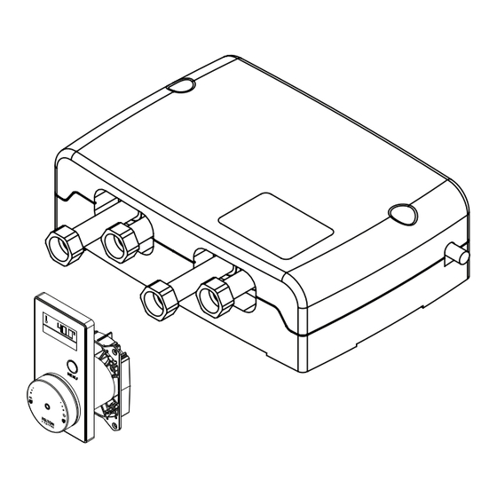
Draw wire through the Control Housing The draw wire should be fitted before the wall is lined. NOTE: Feeding a string or wire through the Control Housing and conduit will make it easier to pull the cables through to the TLC 30 FTD. Conduit (not supplied) Wire (not supplied) DIGITAL MIXER INSTALLATION Remove the cover AXISS DIGITAL SMARTVIEW INSTALLATION GUIDE... - Page 10 Inside the Temperature & Flow Control Unit Connector block Power supply Battery compartment Fixing holes Cover retaining holes Connects to hand shower Connects to fixed head COLD Outlet Inlets FELTON...
- Page 11 MOUNTING OPTIONS Refer to Scope of Application on p6 for the plumbing layout Mark the position of the Temperature & Flow Control Unit fixing holes in the selected location ORIENTATION FOR WALL SITUATION: Important: The location of the Temperature & Flow Control Unit must be acessible and dry. Use the processor template on the last page to mark the position of the fixing holes in the selected location.
- Page 12 Remove the inlet adapter retaining bolt Connect hot and cold water supply Fully insert the inlet adapters into the inlet valves (one long and one short adapter). Connect hot and cold water supply IMPORTANT: Flush the Insert inlet supply pipework before connection Tighten adapter retaining bolt FELTON...
- Page 13 Remove the outlet adapter retaining bolts Connect outlet pipeworks Insert outlet adapters and connect outlet pipeworks If using two outlets: If only using single outlet: Connect outlet and outlet Outlet to be connected. Outlet to be plugged and sealed. Primary outlet (Hand Shower) Secondary outlet (Fixed Head) AXISS DIGITAL SMARTVIEW INSTALLATION GUIDE...
-
Page 14: Vision Wheel Interface Final Fit Installation
Tighten adapter retaining bolt DISPLAY UNIT AND CONTROL WHEEL FINAL FIT INSTALLATION 13 Fit off after final wall lining is installed Finish the wall by tiling etc. 40mm diameter holes should be drilled in the tile etc to finish. Draw a line around the collar, flush with the wall. Cut down the collar as marked. Final wall lining Final wall lining FELTON... - Page 15 Attach steel clip Fix the control steel clip to the wall where shown using the fixings supplied. 56mm Steel clip ø 5 m m 60mm 110mm 60 m m 40mm Feed both cables through to Temperature & Flow Control Unit Remove Control Wheel from the Control Housing. Feed data cable through silicone seal and black foam seal Secure both cables to the previously installed draw wire and pull the cables to the Temperature &...
- Page 16 Position Display Unit and attach with screws Position the Control Housing into the Display Unit and lock by turning clockwise. Push and twist to lock Fit Control Wheel Fit silicone seal ADVICE: Push in firmly! inside the Display Unit FELTON...
- Page 17 18 Connect the Back Up Battery Place back up battery in shown location within the Temperature & Flow Control Unit and connect cable to ACCU port. Note: After installation, battery may require 24 hours of charging on mains power before battery back up function before fully operational. Charging occurs once unit is on mains power. Connect the Control Wheel to the Temperature & Flow Control Unit port TLI-W BODY CONTROL WHEEL GREY CABLE...
- Page 18 GREY CABLE Plug the Display Unit to the RS-232 port as Plug the TLI-W shown body cable to the TLI port as shown Fit the cover back on to the base using a Phillips screwdriver secure the cover in position. The unit is now ready for commissioning. Please see User Guide. IMPORTANT: Electrical supply must be installed by a qualified electrician (if required). FELTON...
-
Page 19: Operational Test
OPERATIONAL TESTING: 1 Ensure that the Digital Mixer is installed correctly installed according to the instructions above. Turn on the water supply and check the unit and plumbing for leaks. Once the plumbing is confirmed to be water-tight, connect the power suply and conduct the operational test below. 2 Open Close Push the Smartview™ Interface once. Push the Smartview™ Interface again. The Digital Mixer opens and the LED illuminates. The Digital Mixer closes and the LED goes off. -
Page 20: Troubleshooting
Carry out function «Self Check Diagnosis» The interface is defective On Smartview User Guide adjustment The knob is not running smoothly Remove and clean knob If issue persists or is not covered in the above, please contact our Felton Technical Team on 0800 743 358 or sales@felton.co.nz FELTON... -
Page 21: Warranty
WARRANTY 5 year warranty applies to all Felton branded products including the electronic hardware and its components. Where products are promoted as having a “5 year warranty”, Felton Industries Limited guarantees the electronic components of these products (excluding batteries) to be free from defects in materials and workmanship under normal installation, use and service for a period of five (5) years from the date of purchase. Fair wear and tear is expressly excluded. This warranty is effective for five (5) years from the date of purchase and covers electronic replacement parts only (excluding batteries) and 2 years from the date of purchase for plumber’s labour relating solely to repairing or replacing the Hardware, provided the product is installed by a registered plumber. You must retain proof of purchase of the Hardware (such as an invoice or receipt) and proof of installation by a registered plumber and provide these to Felton on request. This warranty is for manufacturing defects only and does not cover any damage to product due to abuse, negligence or improper installation. This warranty is given on the understanding that the product is installed by a registered plumber and operated according to Felton’s installation guide and the Australian/New Zealand... - Page 22 FELTON...
-
Page 23: Processor Template
SMARTVIEW™ PROCESSOR TEMPLATE AXISS DIGITAL SMARTVIEW INSTALLATION GUIDE... - Page 24 @ f e l t o n . c o . n z | F i n d u s o n S o c i a l M e d i a @feltontapware /feltonltd /FeltonIndustriesLimited @feltonltd /felton-industries-limited 150322EI FELTON...
Need help?
Do you have a question about the Axiss Smartview FD-SVCSMC and is the answer not in the manual?
Questions and answers