
Related Manuals for FlySky Paladin PL18 EV


Summary of Contents for FlySky Paladin PL18 EV
- Page 1 U s e r M a n u a l U s e r M a n u a l Copyright ©2022 Flysky Technology co., ltd Website...
- Page 2 If you encounter any problems during using, please refer to this manual first. If the problem is still not resolved, please contact the local dealer directly or contact the customer service staff via the website below: http://www.flysky-cn.com...
-
Page 3: Table Of Contents
Table of Contents 1. Safety ............1 7.4.1 Bind Setting ................21 1.1 Safety Icons ...............1 7.4.2 Custom Port Protocol ............21 1.2 Safety Guide ..............1 7.4.3 Failsafe .................21 2. Battery Safety Instructions ......2 7.4.4 Range Test ................22 3. Product Description .........3 7.4.5 PWM Frequency ..............23 3.1 System Features ..............3 7.4.6 Low Signal Voice Alarm .............24 3.2 Transmitter Overview ............4... - Page 4 7.21.6 RF Firmware Updating ...........46 7.22.13 TX Firmware Update............50 7.22 System ................46 7.22.14 About Paladin EV ............50 7.22.1 Language ................46 7.23 Hlep Center ..............51 8. Product Specifications ......52 7.22.2 Units ..................46 7.22.3 Sound ................47 8.1 Transmitter Specifications(PL18 EV) ......52 7.22.4 Vibration ................47 8.2 Receiver Specifications (FGr12B)...
-
Page 5: Safety
1. Safety 1.1 Safety Icons Pay attention to the following icons and their meanings. Failure to follow these guidelines can result in equipment damage or personal injury. WARNING • Not following these instructions may lead to minor injuries. CAUTION • Not following these instructions may lead to major injuries. -
Page 6: Battery Safety Instructions
2. Battery Safety Instructions Danger Danger This products battery is rechargeable Do not charge batteries that show and non-removable. Do not remove any evidence of damage, aging, the battery from the product. leakage or exposure to liquids. Do not expose the battery to liquids. Do not touch the positive and negative terminals of the battery together. -
Page 7: Product Description
3. Product Description PL18EV is an 18-channel transmitter dedicated to engineering vehicles, equipped with 2.4GHz AFHDS 3 (third- generation automatic frequency hopping digital system). 3.1 System Features AFHDS3 (third-generation automatic frequency hopping digital system) is a newly developed digital wireless system. -
Page 8: Transmitter Overview
3.2 Transmitter Overview Front View [20] [21] [22] [23] [24] [25] [26] [27] [10] [28] [11] [29] [30] [12] [31] [13] [32] [14] [33] [15] [34] [16] [17] [35] [18] [36] [19] TR3 Trim SWC Self-locking button Antenna [13] [25] Screen TR5 Trim Transmitter Status Indicator... - Page 9 Back View [37] [44] [38] [45] [39] [46] [40] [41] [47] [48] [42] [49] [43] [50] [37] Carry Handle [44] Micro USB interface [38] Bluetooth Module Interface [45] Trainer Interface [39] FRM301 Status Indicator [46] Press to Release FRM301 [40] FRM301 Button [47] FRM301 RF Module...
-
Page 10: Transmitter Antenna
Reset button Reset button The reset button is on the lower part of the transmitter as shown above. You need to tear apart the grip to find it. To press it by using a long thin tool, such as a smaller screwdriver. In case of the transmitter can not be powered off by pressing the two Power Switches, please reset the transmitter with the Reset button. -
Page 11: Stick/Knob/Button/Trim
states: gradual light, flashing, and solid on. When the screen is on: • If RF is enabled without connecting the receiver (one-way binding with the receiver), the blue indicator is solid on. • If RF is disabled, the yellow indicator is solid on. •... -
Page 12: Power Switches
Function Settings: By adjusting the tension screws on the back of the transmitter, gimbal stick can be either self-centering or non self-centering, as well as changing stick tension preference. To change the gimbal sticks self-centering or non self- To change vertical tension strength of Available options: ①... -
Page 13: Receiver Overview
3.3 Receiver Overview(Take FGr12B as an example) CH9(NPD) CH8-CH2 PPM/CH1 VCC/BVD -(Power cathode) +(Power anode) S(Signal pin) Antenna S(Signal pin) BIND button -(Power cathode) (CH12/NPA) CH11(NPB) CH10(NPC) +(Power anode) 3.3.1 Receiver Antenna The FGR12B uses AFHDS 3 (third generation automatic frequency hopping digital system), which enables bi- directional transmission. -
Page 14: Pre-Operation Setup
4. Pre-operation Setup Follow the instructions and guidelines in this chapter before use. 4.1 Receiver and Servo Installation Make sure that the receiver is mounted in an appropriate location within the model, to ensure a stable signal, maximum range and to mitigate external interference, follow these guidelines: Pay attention to the following when installing the receiver: 1. -
Page 15: Operation Guidelines
The transmitter and the receiver have been pre-bound at the factory. If you need to rebind or bind a new receiver follow the steps below. The Flysky AFHDS 3 receivers are consisted by classic version receivers and enhanced version receivers. The bind method is slightly different between these two versions. - Page 16 5. Check to make sure the transmitter and the receiver are working correctly, repeat steps 1 to 3 (binding process) if any problems arise. Notes: The receiver may vary with different models, visit FLYSKY official website for more details. When you select Routine 18ch, with choosing Two way connection and Mul RX(Multi-receiver), the transmitter supports multi-receiver mode.
-
Page 17: Pre-Operation Checks
5.3 Pre-operation Checks Always perform the following steps before each operating: 1. Inspect the entire system to make sure that everything is working as expected. 2. Perform a range test as outlined in the Range Test section of this manual. DANGER •... -
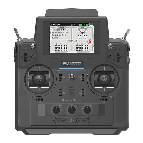
Page 18: Ui Overview
6. UI This is an introduction to the transmitter's UI. 6.1 UI Overview The main interface displays information related to the model such as sensor information and function status. Displays signal strength, the receiver is not TR8 trim connected,or the RF is disabled. Lock screen icon Display signal strength, when a receiver is connected in two-way. -
Page 19: Menu Ui
6.2 Menu UI This section is a quick introduction on how to use the UI. 6.2.1 Function Icons Screen/Function is Locked Screen/Function is unlocked. Function is disabled. Function is activated. Restore to the default setting. To increase the value. Assign switches To decrease the value. -
Page 20: Function Settings
7. Function Settings This chapter introduces the main system functions. 7.1 Disp servos To display the real-time output value of each individual channel, and activate the mode of testing all 18 channels. Display Servos Function Settings: 1. Tap Disp servos to enter the display servos menu. - Page 21 Assigning Function Items To select a function which need to be assigned a control. Function Settings: 1. Tap the function that needs to be set and enter the menu. 2. Tap an appropriate function. 3. If you want to create a auxiliary channel for the control, tap Custom:(AUX.1) and enter an appropriate name on the pop- up munu using the soft keyboard.
-
Page 22: Model Setting
position is in the low position and 100% when the control position is in the high position (the neutral position control ratio in the three-level switch is 0%). It is conversely for Reverse. In other words, the control ratio of SW switches is 100% in the low position and -100% in the high position. -
Page 23: Switch Model
7.3.2 Switch Model This function allows you to switch models. The system can store 20 groups of model data, including all setting data except system settings. Function Settings: You can directly select the model to be used in the list, and select Yes in the pop-up dialog box to switch the model. -
Page 24: Custom Main Menu
7.3.8 Import or Export Model To import or export the model. Function Settings: Click to import/export the model. You need to log in to the FLYSKY official website to download the software (Flysky Assistant V3.0) and then operate it on a PC! Website... -
Page 25: Rx Setup
3. For the receivers with SENS interfaces, i-BUS/Servo does not support i-BUS-IN. The menu of multi-receiver 7.4.3 Failsafe For failsafe function, paladin PL18 EV transmitter provides the following three settings: • Set to disable the signal output of i-BUS-out and PPM protocol interfaces in case of out-of-control, i.e., no... -
Page 26: Range Test
• New Added item: Set Failsafe for all channels set to fixed values. With this function, With this function, you can set the output values of all channels controlled by a control to the current value, and this value will be output when the system is losing control. -
Page 27: Pwm Frequency
and receiver is far, in practice, it is difficult to pull the transmitter and receiver far enough away to verify whether the RF is normal. Therefore, when this function is enabled, it can test whether the transmitter and receiver are normal at a close distance. -
Page 28: Low Signal Voice Alarm
PWM Frequency-Enhanced Receiver Set PWM frequency after the transmitter is bound to enhanced receivers. Set all channels. Function Settings: Tap Set all channels. 2. Tap an appropriate item according to the actrual servo. 3. For Custom, click + / - to set an appropriate frequency value. -
Page 29: Bvd Voltage Calibration
Function Settings: Enter the Low voltage voice menu. Click an appropriate item according to what you want to set. Then click to return. 3. Tap Battery Type to enter the setting menu, then click an appropriate battery type. 4. Click + / - to set an appropriate voltage according to the actual device. -
Page 30: Config Rx As A Pwm Converter
7.4.9 Config RX as a PWM Converter Set the receiver as a PWM converter for PWM channel expansion. After the setting is successful, the receiver is used as a PWM converter, and its interfaces output PWM signals. Function Settings: Eenter Set as PWM converter menu. -
Page 31: I-Bus Setting
7.4.10 i-BUS Setting This function is used to set the external device with supporting i-BUS protocol, and the Serial Bus Receiver (FS-CEV04) and can be set currently. When using i-BUS serial bus receiver, it reccomends to power it separately. Function Settings: 1. -
Page 32: Receiver Update
7.4.12 Receiver Update To update the firmware of the receiver. PL18 EV transmitter packs the firmware of FGr12B, FGr8B, FTr10, FTr16S, FGr4 and FTr4/FGr4S/FGr4P. It can also be updated via FlyskyAssistant. Please note that this function is applicable for the FlyskyAssistant firmware version 3.0 or above. Function Settings: 1. -
Page 33: Sensors
7.5 Sensors This function allows you to set the transmitter, internal receiver and data returned by the external sensor. 7.5.1 Display Sensor Display the sensor type drops below 11, reduce the range quickly to • TX Voltage: To display the voltage for the prevent loss of control. -
Page 34: Choose Sensors
7.5.2 Choose Sensors This function is used to set the sensor data displayed on the main interface, and to enable setting the current sensor alarm threshold. Function Settings: 1. Tap a item from the list and enter its menu. 2. Tap to enable the alarm function as well as setting a customize alarm value. - Page 35 FS-CPD01: Magnetic induction speed acquisition module Used to measure the speed of the motor. Connect it to the NPA interface of the receiver directly. Then view the real- time information via Dispaly sensors function. Function Settings: Sensor 1. Connect the FS-CPD01 sensor to the NPA interface of the receiver.
- Page 36 Function Settings: 1. Connect the FS-CTM01 sensor to the NPA interface of the receiver. 2. Use soft double-sided tape to attach the FS-CTM01 to element you want to measure (e.g., motor, battery). Make sure the sensor is pressed against the surface snugly. 3.
-
Page 37: Air Pressure Sensor
7.5.3 Air Pressure Sensor Calibrates ground pressure. Function Settings: 1. Connect the FS-CAT01 sensor to the NPA interface of the receiver, then place the model on the ground. Use + or – to adjust the altitude. Note: Make sure your model is always at a level ground level during setup. -
Page 38: Subtrim
Function Settings: 1. Enter End point menu. 2. Tap the item you want to set, then click + / - to change the value. Tap to return. 7.8 Subtrim This function is used to adjust the center point of each channel. Due to the structure of some models the servos center point may need to be adjusted so that when at rest all the control surfaces line up properly. -
Page 39: Trims
7.10 Trims You can view the trim values that assigned functions. For TR1 to TR8, you can set the appropriate Step value, Trim mode and Trim value, whether for current condition or all condition. And for VR kind traim, you can only set the Trim mode and Trim rate. -
Page 40: Dr Setup
Function Settings: 1. Tap the function you want to set. 2. Select EXP2, LINE . 3. Tap the function item you want to set. 4. Click + / - to change to an appropriate value. Tap return. 7.12 DR Setup Note: This function is available for version 1.0.28 or above. -
Page 41: Channels Delay
7.14 Channels Delay This function is generally used to reduce the instantaneous large speed of the servo. Function Settings: 1. Click the channel you want to set. 2. Click + / - to change the delay time to an appropriate point, then click to return. - Page 42 Setting Master Used to set related settings of Master. You can set one control or function as the Master. Function Settings: 1. Tap the function box next to Master to enter. 2. Tap Stick or Knob to enter if you want to set Master to a control.
-
Page 43: Track Mixing
Curve Used to set the mix rate for the channel in current condition. If the Curve needs to be set for other conditions, switch to other conditions prior to settings. Function Settings: 1. Enter Curve setting menu. 2. Click Line type to set the appropriate line type. 3. - Page 44 pressure by 60% from each pulse in real-time when braking is triggered. Function Settings: 1. Tap Return. 2. Click + / - to change to an appropriate value. Delay To set the time from trigger the pulse brake to actually pulse brake between 0% to 100%.
-
Page 45: Timers
Duty Used to set the braking to release cycle length in pulse braking between -4 and +4. The default valus is 0. When the value is changed, the peak and trough lengths of the brake pulse's square wave change accordingly. You can adjust the rate between braking and release. -
Page 46: Model Timer
7.18.2 Model Timer Used to calculate total working time of the model. Function Settings: 1. Tap Model timer to enter, then tap to activate the function. 2. To reset the accumulated time, click Reset to reset the timer. 7.18.3 Sound Prompt This function can be selected according to the needs of the voice prompt Timers 1 or Timers 2. -
Page 47: Logic Switches
7.20 Logic Switches This function changes the output curve for the throttle channel. A curve can be created using 3 – 11 different points so that the user has much better control of the model's engine. The setting is for current condition, for the settings of other conditions, switch to other conditions first, and then carry out the settings. -
Page 48: Rf Setup
7.21 RF Setup Used to set and display some parameters and information related to RF, such as RF type, RF module firmware update, RF module version information related content. 7.21.1 Transmit Select this option to enable the RF function. By default, it is enabled. -
Page 49: Rf Type
7.21.4 RF Type Used to select an appropriate RF type as per the communication protocol of the receiver which is bound with the transmitter. FRM301 (classic receiver) and FRM302 (enhanced receiver) are compatible with AFHDS 3 protocol; PPM is for RF module using PPM protocol, and CRSF for RF module using CRSF protocol. -
Page 50: Rf Firmware Updating
4. Tap Starting level, then click + / - to set an appropriate value. Click to return. 7.21.6 RF Firmware Updating To upgrade the RF firmware . It is only available when the RF type is set to FRM301. Function Settings: 1. -
Page 51: Sound
7.22.3 Sound To turn on or off system sounds, alarm sound, Off/on sound. Function Settings: 1. Enter Sound setting menu. 2. Tap the sound item, if the √ appears, indicating the sound is on, otherwise, the sound is off. 3. Click + / - to change the volume, then click to return. -
Page 52: Backlight Brightness
7.22.6 Backlight Brightness To adjust the brightness of the screens backlight. Function Settings: 1. Enter Backlight brightness setting menu. 2. Click + / - to change to an appropriate value, then click to return. Note: Turning the brightness up will use more power and as such will lead to reduced battery life. -
Page 53: Screen Quick Access
7.22.9 Screen Quick Access Used to set up the up, down, left and right shortcut screen sliding functions of the mainmenu. Users can customize the screen sliding menu according to their requirements. Function Settings: 1. Enter Screen quick access setting menu. 2. -
Page 54: Factory Reset
7.22.12 Factory Reset To reset the transmitter to its factory default state. This deletes all data including all model data and system settings. Function Settings: Tap Factory reset, a pop-up window comes alone, click Yes to finish. 7.22.13 TX Firmware Update Used tp put the transmitter into firmware updating state. -
Page 55: Hlep Center
7.23 Hlep Center To obtain the user manual via this function. Users can contact us through social accounts listed on the menu. Function Settings: 1. Tap Help center to its setting menu. 2. Tap the item you want to view, then the corresponding QR code will be displayed. -
Page 56: Product Specifications
8. Product Specifications This section describes the PL18 EV transmitter, FGr12B receiver, and sensor type receiver. 8.1 Transmitter Specifications(PL18 EV) Product Model PL 18 EV Product Name Paladin EV Channels Adaptable receivers All receivers with AFHDS 3 protocol Model Type Engineering vehicles, simulation ships, etc. -
Page 57: Receiver Specifications (Fgr12B
8.2 Receiver Specifications (FGr12B) FGr12B Model Type FGr12B PWM Channels 2.4GHz ISM 2.4GHz Protocol AFHDS 3 Distance ≥ 300m (Ground distance without interference) Antenna Type Single antenna Power 3.5 ~ 9V/DC RSSI Data Interface i-BUS/S.BUS/PPM/PWM Temperature Range -10℃ ~ +60℃ Humidity Range 20% ~ 95% Online Update... -
Page 58: Package Contents
9. Package Contents Number Name Quantity Configuration Remarks PL18 EV Transmitter Standard QUICK START GUIDE Standard FGr12B Receiver Standard FRM301 RF Module Standard Thin grip Standard RF fixed plate Standard Standard LOGO sticker 1 Standard LOGO sticker 2 Standard Fuselage stickers for PL18 EV Standard 1 in orange, 1 in yellow, Button switch rubber cover... -
Page 59: Certification
10. Certification 10.1 DoC Hereby, [Flysky Technology co., ltd] declares that the Radio Equipment [Paladin(PL18 EV),FT18 EV] is in compliance with RED 2014/53/EU. The full text of the EU DoC is available at the following internet address: www.flysky-cn.com 10.2 CE Warning The antenna(s) used for this transmitter must be installed to provide a separation distance of at least 20 cm from all persons and must not be co-located or operating in conjunction with any other transmitter. -
Page 60: Environmentally Friendly Disposal
11. Environmentally friendly disposal Old electrical appliances must not be disposed of together with the residual waste, but have to be disposed of separately. The disposal at the communal collecting point via private persons is for free. The owner of old appliances is responsible to bring the appliances to these collecting points or to similar collection points. - Page 61 Copyright ©2022 Flysky Technology co., ltd 出版日期 :2022-06-01 Website CE, FCC ID: N4ZFT1800 Manufacturer:ShenZhen FLYSKY Technology Co., Ltd Address: 16F, Huafeng Building, No. 6006 Shennan Road, Futian District, Shenzhen, Guangdong, China...
Need help?
Do you have a question about the Paladin PL18 EV and is the answer not in the manual?
Questions and answers