
Related Manuals for FlySky FS-ST8


Summary of Contents for FlySky FS-ST8
- Page 1 FS-ST8 USER MANUAL USER MANUAL Digital Proportional Radio Control System Copyright ©2022 Flysky Technology co., ltd...
- Page 2 If you encounter any problems during using, please refer to this manual first. If the problem is still not resolved, please contact the local dealer directly or contact the customer service staff via the website below: http://www.flysky-cn.com...
-
Page 3: Table Of Contents
Contents 1 . Sa fet y ..............1 1 .1 Sa fet y Symb ols .. - Page 4 6.3.2 MDL SET - RATE/CURVE ....................17 6.3.3 MDL SET - THROTTLE CURVE ..................18 6.3.4 MDL SET - THROTTLE HOLD ..................18 6.3.5 MDL SET - V-TAIL ......................18 6.3.6 MDL SET - DELTA-WING MIX ..................18 6.3.7 MDL SET - TRACK MIX ....................19 6.3.8 MDL SET - PITCH CURVE ....................
-
Page 5: Safety
1.Safety 1.1 Safety Symbols Pay close attention to the following symbols and their meanings. Failure to follow these warnings could cause damage, injury or death. Danger • Not following these instructions may lead to serious injuries or death. Warning • Not following these instructions may lead to major injuries. -
Page 6: Introduction
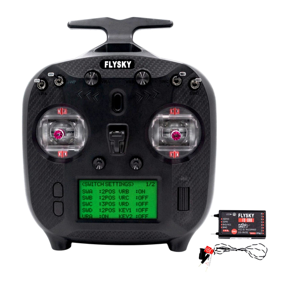
FS-ST8 Digital Proportional Radio Control System 2.Introduction This product uses the 2.4 GHz ANT (Ant Protocol) automatic frequency hopping digital system, consisting of FS- ST8 transmitter and FS-SR8 receiver. It has an output of 8-10channels, compatible with model fixed-wing aircraft, delta-wing airplanes, helicopters, gliders, multicopters, engineering vehicles, robots, etc. -
Page 7: Button/Scroll Wheel
2.1.1 Button/Scroll Wheel Operation Instructions for MENU, EXIT and Scroll Wheel. MENU button • Press MENU in the main page to enter the function menu. • Press and hold MENU for seconds to enter MONITOR menu. EXIT button • Press EXIT to return to the previous menu. In the editing state, you can press EXIT to save and exit the editing state. -
Page 8: Rece I Ve R Over V Iew (Fs -Sr8)
FS-ST8 Digital Proportional Radio Control System 2.2 Receiver overview (FS-SR8) [13] [14] [15] [16] [15] [14] [13] [20] [19] [12] [11] [10] [21] [17] [18] [1] CH1/PPM [8] CH8 [15] Signal pin [2] CH2 [9] BIND interface [16] LED [3] CH3... -
Page 9: Getting Started
3. Getting Started Prior to operations, please install the battery and connect devices according to the sequence and guide as described in this chapter. 3.1 Installing Transmitter Battery Danger • Only use specified battery (X4 AA batteries). Danger • Do not open, disassemble, or attempt to repair the battery. Danger •... -
Page 10: Operation Guide
• Applicable to the FS-ST8 transmitter and the FR-SR8 receiver. Different receivers have different bind procedures. For more information visit the FLYSKY website for manuals and other related information. • Product information is updated regularly, please visit our website for more information. -
Page 11: Stick Calibration
4.4 Stick Calibration The calibration is required in case of data offset of the transmitter due to physical wear in long-term operations. At this time, we need to calibrate the output data and neutral angle of the stick, throttle trigger, and potentiometers. The transmitter has been calibrated at the factory. -
Page 12: Main Menu
FS-ST8 Digital Proportional Radio Control System 5. Main menu Instructions are about the main menu. Status bar: To show the signal strength and TX voltage. When the receiver is bound, and the voltage of the receiver is 6V, then RX6.0V will displayed here. SENSORS The icons shown here indicate that the function is enabled, Lock icon, Flight mode icon, Throttle hold Note: Up to three icon and GPS icon. sensors' information can be displayed here. T3/T4 Trim T1/T2 Trim Model name and the number Timer Quick access to the menu:... -
Page 13: Function Menu
6. Function menu In this transmitter, we have classified the functions and made a new layout. There are 4 categories in icons in total. That is: TX SET(Transmitter Settings), RX SET(Receiver Settings), MDL SET(Model menu), GENER MENU(General menu). After the classification, it will become more convenient and easy to set up the model next-level menu may vary with different model type, and lists below: For DELTA-WING: CONDITIONS, RATE/CURVE, THROTTLE CURVE, THROTTLE HOLD and DELTA-WING MIX;... -
Page 14: Transmitter Settings
FS-ST8 Digital Proportional Radio Control System 6.1 Transmitter settings There are 11 function menus in TX SET menu: MODEL, TRAINER, STICK MODE, CALIBRATION, SYSTEM SETTINGS, TIMERS, SWITCH SETTINGS, FIRMWARE UPDATE, ABOUT, HELP CENTER, MORE and FACTORY RESET. In the main menu, press MENU to enter the function menu. Selec TX SET by scrolling... -
Page 15: Tx Set - Trainer
When the switch is off, the student controls the aircraft. For example, if the trainer and the student use two FS-ST8 transmitters for teaching and training. The trainer's FS-ST8 transmitter needs to be set to ON for this function with a control switch, and the student's transmitter does not need to be set. -
Page 16: Tx Set - System Setting
FS-ST8 Digital Proportional Radio Control System 6.1.4 TX SET - SYSTEM SETTING The system setting function is used to set the transmitter system, including setting the language, sound, volume, alarm time, vibration, vibration grade, battery type, LED color, LED, brightness, time of backlight and autoshutdown. -
Page 17: Tx Set - Timers
6.1.5 TX SET - TIMERS The Timer function is used for timing in races, including count up and countdown. You can also use it to test a tank of fuel or a full battery and confirm the usage time. The transmitter provides two timers, which can be set independently to achieve different timing functions. -
Page 18: Tx Set - About
FS-ST8 Digital Proportional Radio Control System 6.1.8 TX SET - ABOUT Used to display the system information, such as hardware version, etc. Function settings: Select ABOUT and press Scroll Wheel to enter, then you can view the related information. 6.1.9 TX SET - HELP CENTER To obtain the user manual via this function. -
Page 19: Rx Set - Failsafe
FREQUENCY To set an apppropriate frequency according to your servos. Note: Note: When the frequency value is set to 50HZ, it presents the analog servo, and set to 333HZ, it is for digital servo. For other servo, set the value in the range between 50 and 400HZ. RF STANDARD There are two options available, ANT1WAY one-way and ANT2WAY two-way. If you are using a two- way receiver, it is recommended to select ANT2WAY two-way, which may bring you a better experience with more information feedback. -
Page 20: Rx Set - Rf Settings
6.2.7 RX SET - GPS SETTING This function needs to be used with the GPS sensor of FLYSKY. You can view the information returned by GPS sensor after calibrating the GPS and setting an appropriate time. You can reset the start point when the displayed distance is inaccurate. -
Page 21: Mo De L S Ett I Ng
RESET START POINT To reset the start point when the displayed distance is inaccurate. Function settings: 1. Select GPS SETTING and press Scroll Wheel to enter. Select GPS DISPLAY and press Scroll Wheel to display the related information. Select GPS CALIBRATION and press Scroll Wheel to enter. Select CALIBRATION and press Scroll Wheel to start. Select RESET START POINT and press Scroll Wheel, the system will pop-up a menu, select OK press Scroll Wheel to finish. 6.3 Model settings Used to set the functions related to the model. The functions vary with different models. All functions are CONDITIONS, RATE/CURVE, THROTTLE CURVE, THROTTLE HOLD, PITCH CURVE, HELI PITCH SETUP, GYROSCROPE, DELTA-WING MIX,V-TAIL and TRACK MIX. -
Page 22: Mdl Set - Throttle Curve
FS-ST8 Digital Proportional Radio Control System 6.3.3 MDL SET - THROTTLE CURVE It is a function specifically for throttle channel to achieve the perfect match between throttle output and motor or engine. It can be set individually in different flight conditions, with 7 dynamic adjustment points throughout the travel. -
Page 23: Mdl Set - Track Mix
6.3.7 MDL SET - TRACK MIX This function is set for some specific models, for example, tank models, excavator models. Two tracks can be driven in the same direction or in the opposite direction. At this time, the track mixed control function can be used. Function settings: 1. -
Page 24: G E N E Ra L S Ett I N G
FS-ST8 Digital Proportional Radio Control System 6.4 General settings Used to set or adjust the general functions which are commonly use inculding MONITOR, REVERSE, END POINTS, CH SPEED, AUX CH, TRIMS and MIXES. In the main interface, press MENU to enter the function menu. Select GENER MENU by scrolling... -
Page 25: Gener Menu - Ch Speed
6.4.4 GENER MENU - CH SPEED This function can be used to adjust the output speed of some channels for a specific model. For example, in the landing gear retraction, users may want it to be opened slowly, therefore, you can slow down the output speed of the corresponding channel. - Page 26 FS-ST8 Digital Proportional Radio Control System OFFSET To set the offset value of the slave chanel. Function settings: 1. Select MIXES and press Scroll Wheel to enter. Set ON or OFF to turn on or turn off using Scroll Wheel. 3. Set a switch. In the menu, select a switch and its corresponding position to finish, or you can toggle the corresponding physical switch on the transmitter to finish. Set a channel for M or S using Scroll Wheel. Set appropriate values for NOR, REV and OFFSET using Scroll Wheel. Press EXIT to save and exit.
-
Page 27: Fs-Sr8 Function Instructions
7.4 Updating the Firmware of the Receiver The firmware of this receiver is updated through the FlyskyAssistant (Only version 3.0 or above is supported. The firmware of FlyskyAssistant is available on the Flysky official website). This receiver can be updated via the following two ways: After the binding between the transmitter and the receiver (the LED of the receiver is solid on), connect the transmitter to thecomputer, then open the FlyskyAssistant on the computer to update the firmware. -
Page 28: Diy Customization
8.1 Throttle Bracket Installation FS-ST8 transmitter has two sticks in the factory settings, and one is the self-return stick. To use the non-self-return stick, please follow the steps below to replace the self-return stick to the non-self-return stick. The throttle spring includes two types: setback spring and non-setback spring (the installation steps are the same). - Page 29 Pay attention to the bending direction of the bracket. 5. Remove the spring hook assembly carefully. 7. Put the bracket to the position which is shown above, then secrew it using the screws. You can install the setback spring or non-setback spring here. If the screws are too tight or too loose, this may bring different hand handle. 8. Carefully insert the back cover wiring plug into the motherboard, re-close the transmitter back cover, and tighten the screws. 6. Place the plate assembly back in its original position, then secure it with the original 4 screws.
-
Page 30: T H Rottl E S P R I N G I N Sta L L At I O
FS-ST8 Digital Proportional Radio Control System 8.2 Throttle Spring Installation The following instructions explain how to change the non self-return to self-return. 1. Take the transmitter apart and remove the gimbal, then remove the two screws which are shown above and remove the bracket. 4. Place the spring hook assembly into position and hook the spring onto the hook located inside the transmitter. 2. Loosen the assembly screws shown above first, then remove the plate assembly. Be careful to ensure no damage to cables. 5. Place the plate assembly back in its original position, then secure it with the original 4 screws. 3. Insert the 2 dowels as shown above. -
Page 31: S Wa Pp I Ng G I M Ba L
8.3 Swapping Gimbals When changing between modes 2/4 (M2/M4) and modes 1/3(M1/M3), you will need to switch the gimbals around so that the throttle gimbal is on the correct side. 3. Reassembly the transmitter. 1. Take the transmitter apart using a screwdriver, remove the 8 screws marked in red. 4. Turn on the transmitter and make sure everything is working as expected via Main menu > GENER MENU> MONITOR. 2. Swap the gimbals and rotate them 180 degrees, then line them up with the screw holes and secure the screws. (There is no need to disconnect the cables.). -
Page 32: D Ev I Ce H O Ld E R I N Sta L L At I O
FS-ST8 Digital Proportional Radio Control System 8.4 Device Holder Installation Mobile devices, such as mobile phone, can be used in real time to receive information from an aircraft, it may be fitted into the mobile device bracket for your convenience. -
Page 33: Stea L Th I/O R F M Od U L E A Da Pte R I N Stal L At I
8.5 Stealth I/O RF Module Adapter Installation If you have purchased the RF head adapter, fix it on the transmitter by following the steps below: 1. Place the left and right RF module adapters as 2. Tighten the four screws to secure the RF module shown in the figure. Remember to align the screw adapters. holes. Note: The transmitter Stealth I/O RF module interface is designed without power supply, Stealth I/O RF module interface pins are defined as shown in the figure below. If you connect the RF module externally through the RF module adapter, you need to supply power to the RF module separately. PPM/TX S.port Stealth I/O RF module interface... -
Page 34: An Te N Na A Sse M B L Y I N Sta L L At I
FS-ST8 Digital Proportional Radio Control System 8.6 Antenna Assembly Installation If you have purchased 2.4G antenna assembly inner-screw-inner-hole, the installation procedure is described below. Remove the antenna hole plug small adhesive piece with the help of tweezers and other tools along the direction as shown. -
Page 35: Product Specifications
9. Product Specifications This section contains FS-ST8 transmitter and FS-SR8 receiver specifications. 9.1 Transmitter specification(FS-ST8) Product Model FS-ST8 Channels 8-10 Adaptive receiver FS-SR8 ( Adapts receiver with ANT protocol ) Fixed-wing aircraft, Helicopters, Gliders, Delta-wing airplanes, Multicopters, Racing Model Type drones, Engineering vehicles, Robots, Cars or Boats, etc. -
Page 36: Re Ce I Ve R Sp E C I F I Cat I O N (Fs -S
Digital Proportional Radio Control System 9.2 Receiver specification(FS-SR8) Product Model FS-SR8 Adaptive transmitter FS-ST8 (Adapts transmitter with ANT protocol ) Fixed-wing aircraft, Helicopters, Gliders, Delta-wing airplanes, Multicopters, Racing Adaptive Models drones, Engineering vehicles, Robots, Cars or Boats, etc. Numbers of channel Maximum Power <... -
Page 37: Package Contents
10. Package Contents This section contains packing list information. Different versions have different configurations, please consult your dealer for details. For Standard Edition Number Name Quantity Remark FS-ST8 Transmitter FS-SR8 Receiver Quick start guide For Upgraded Version Number Name Quantity... -
Page 38: Certifications
11. Certifications 11.1 DoC Declaration Hereby, [Flysky Technology co., ltd] declares that the Radio Equipment [FS-ST8] is in compliance with RED 2014/53/ The full text of the EU DoC is available at the following internet address: www.flysky-cn.com. 11.2 CE Warning The antenna(s) used for this transmitter must be installed to provide a separation distance of at least 20 cm from all persons and must not be co-located or operating in conjunction with any other transmitter. -
Page 39: Environmentally Friendly Disposal
12. Environmentally friendly disposal Old electrical appliances must not be disposed of together with the residual waste, but have to be disposed of separately. The disposal at the communal collecting point via private persons is for free. The owner of old appliances is responsible to bring the appliances to these collecting points or to similar collection points. - Page 40 Copyright ©2022 Flysky Technology co., ltd Release date: 2022-04-11 CE, FCC ID: N4ZST800 Manufacturer:ShenZhen FLYSKY Technology Co., Ltd Address: 16F, Huafeng Building, No. 6006 Shennan Road, Futian District, Shenzhen, Guangdong, China...
Need help?
Do you have a question about the FS-ST8 and is the answer not in the manual?
Questions and answers
How do I Bind a new reciever
bonjour je voudrais imprimer le manuel de flysky fs8-st8 en Français , comment faire