Table of Contents
Advertisement
S
3-759-221-03(1)
®
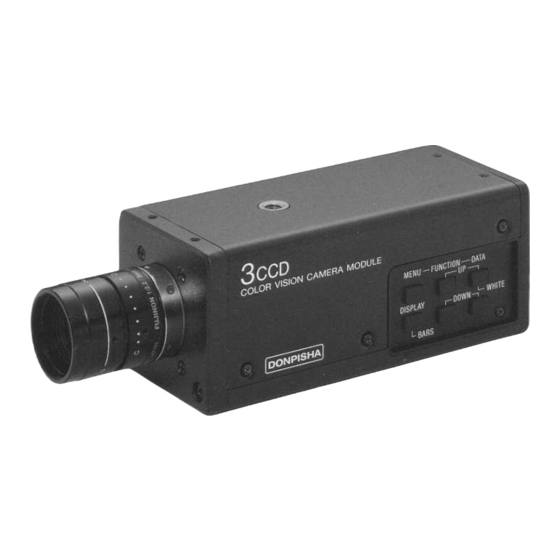
3CCD Color Video Camera Module
3CCD
カラービデオカメラモジュール
Model:
XC-003
XC-003P
取扱説明書
5
ページ
お買い上げいただき、ありがとうございます。
お使いになる前に、この取扱説明書をお読みください。
お読みになったあとは、後日お役に立つこともありますので、
必ず保存してください。
Operating Instructions
Pages 2 and 29
Before operating the unit, please read this manual thoroughly
and retain it for future reference.
© 1994 by Sony Corporation
Advertisement
Chapters
Table of Contents

Related Manuals for Sony XC-003


Summary of Contents for Sony XC-003
-
Page 1: Operating Instructions
3CCD Color Video Camera Module 3CCD カラービデオカメラモジュール Model: XC-003 XC-003P 取扱説明書 ページ お買い上げいただき、ありがとうございます。 お使いになる前に、この取扱説明書をお読みください。 お読みになったあとは、後日お役に立つこともありますので、 必ず保存してください。 Operating Instructions Pages 2 and 29 Before operating the unit, please read this manual thoroughly and retain it for future reference. © 1994 by Sony Corporation... - Page 2 Owner’s Record The model and serial numbers are located on the bottom. Record the model and serial numbers in the spaces provided below. Refer to these numbers whenever you call upon your Sony dealer regarding this product. Model No. Serial No.
- Page 3 Dem Bundesamt für Zulassungen in der Telekommunikation wurde das Inverkehrbringen dieses Gerätes angezeigt und die Berechtigung zur Überprüfung der Serie auf Einhaltung der Bestimmungen eingeräumt. Name und Anschrift des Sony Deutschland GmbH Herstellers/Importeurs: Hugo-Eckener-Str. 20 50829 Köln Hinweis Gemäß dem Amtsblätter des BMPT Nrn. 61/1991 und 6/1992 wird der Betreiber darauf aufmerksam gemacht, daß...
-
Page 5: Table Of Contents
メニューの設定 ... GAIN 例: の変更 ... ページ目のメニューの表示 ... DISPLAY (表示)の切り換え ... 各項目の設定内容 ... 内部スイッチの設定 ... 特有の現象 ... 仕様 ... 特長 本機は、 画像処理用として設計されたカラービデオカメ ラモジュールです( XC-003 は モデル)。 高解像度 水平解像度 570TV 本、感度 2000 lx XC-003 58dB XC-003P ( )、 ( 画像が得られます。... -
Page 6: 使用上のご注意
使用上のご注意 電源電圧 「仕様」に記載してある電源電圧でお使いください。 使用・保管場所 非常に明るい被写体(照明や太陽など)を長時間にわたって 撮影しないでください。 また、次のような場所での使用および保管は避けてくださ い。 極端に暑い所や寒い所 (使用温度は− ● 直射日光が長時間あたる場所や暖房器具の近く ● 湿気、ほこりの多い所 ● 雨のあたる所 ● 激しく振動する所 ● 強い磁気を発するものの近く ● 強力な電波を発するテレビやラジオの送信所の近く ● 放熱 動作中は布などで包まないでください。内部の温度が上が り、故障や事故の原因となります。 お手入れ レンズやフィルターの表面に付着したごみやほこりは、ブ ● ロアーで払ってください。 キャビネットやパネルの汚れは、乾いたやわらかい布でふ ● きとってください。汚れがひどいときは、中性洗剤溶液を 少し含ませた布でふきとった後、からぶきしてください。 アルコール、ベンジン、シンナーなど揮発性のものは使わ ● ないでください。表面の仕上げをいためたり、表示が消え たりすることがあります。 5°C ∼+... -
Page 7: 各部の名称と働き
各部の名称と働き 前面・上面・底面 レンズマウント部 三脚取り付け用 ネジ穴 カメラ固定用 基準穴 (カメラ上部にも同様 に 穴あります。) レンズマウント部( マウント) マウントレンズや光学機器を取り付けます。 三脚取り付け用ネジ穴 カメラの上面と底面に同じ穴があります。壁面や天井にカメ ラを設置するときや三脚を使うときに、このネジ穴を使って 固定します。(ネジ インチ、 山) カメラ固定用基準穴 レンズマウント面に対して、高い精度で加工されたカメラ固 定用の穴です。このネジ穴( 、カメラ部深さ メラを固定すると、光軸のズレを最小限にとどめることがで きます。 )にカ... - Page 8 各部の名称と働き 側面 COLOR VISION CAMERA MODULE MENU ボタン DISPLAY DONPISHA BARS ボタン 4MENU (メニュー)ボタン 条件設定用のメニューをモニター画面に表示するとき、押し ます。もう 度押すとメニューが消えます。 MENU—FUNCTION—DATA WHITE DISPLAY DOWN BARS 5DISPLAY / BARS (ディスプレイ/バー)ボタン メニューで「 GAIN 」 「 WHT BAL 定しているときに押すと、表示形式の切り換え( ← →ページ全体表示)ができます。 メニューを表示していないときに押すと、調整用のカラー バー信号を出力します。 FUNCTION UP ボタン DATA UP/WHITE ボタン...
- Page 9 6FUNCTION UP (ファンクションアップ)ボタン モニター画面に表示されているメニュー上でカーソルを上方 向に移動させるとき、押します。 7DATA UP / WHITE (データアップ/ホワイトバラン ス)ボタン モニター画面に表示されているメニューでデータを設定する ときに使います。押すと、データの値が大きい方に変化しま す。 メニューが表示されていないときは、後面の (オート ホワイトバランス)ボタン と同じ働きをします。 8DATA DOWN (データダウン)ボタン モニター画面に表示されているメニューでデータを設定する ときに使います。押すと、データの値が小さい方に変化しま す。 9FUNCTION DOWN (ファンクションダウン)ボタン モニター画面に表示されているメニュー上でカーソルを下方 向に移動させるとき、押します。...
- Page 10 各部の名称と働き 後面 ボタン !¡ RGB/SYNC LENS VIDEO OUT DC IN/VBS !™ !£ VIDEO OUT !¢ LENS 端子 0AWB (オートホワイトバランス)ボタン 白い被写体を写してこのボタンを押すと、ホワイトバランスが 自動調整され、その値がカメラのメモリーに記憶されます。 / SYNC 端子 !¡RGB / ピン) 信号とその同期信号を出力します。接続には、専用ケー CCXC-9DB ブル い。 ピン番号 DC IN / 端子 端子 SYNC ( 信号/同期信号出力)端子( CCXC-9DD /...
- Page 11 !™DC IN / (電源入力/ 信号出力)端子( カメラアダプターから電源を供給し、 す。外部同期をかけた場合は、 信号を出力します。 外部同期モード ピン番号 / アース 12 V + 映像出力(アース) 映像出力(信号) 入力(アース) 入力(信号) 入力(信号) ―─ ── アース 12 V + 入力(アース) ) 出力、 出力を得るには、内部スイッチの変更が必要です。 ◆ 詳しくは「内部スイッチの設定」( ∼ )出荷時はクロック出力になっていません。クロック出力を得るには、半田付けが必要です。 ◆ 詳しくは、ソニーの営業担当者にお問い合わせください。 ピン) 信号を出力しま カメラ同期信号出力 アース アース...
- Page 12 各部の名称と働き !£VIDEO OUT (映像出力)端子( カメラからの映像を、コンポジットビデオ信号として出力し ます。外部同期をかけた場合は、 !¢LENS (レンズ)端子( ピン) オートアイリスレンズの接続に使用します。 DONPISHA 機能、リスタート/リセット機能を使用する場 合は、外部トリガー入力、 出力用に使用します。 ピン番号 信号 ) DATA / 外部トリガー入力 アース 出力 映像信号出力 + 12 V )フィールドインデックスパルス出力、または外部からのメニューコント ロール用の端子です。 型) 信号を出力します。...
-
Page 13: 使用できるレンズ
設置 使用できるレンズ マウントレンズで、レンズマウント面からの飛び出し量が 4.3mm 以下のものが使用できます。 4.3mm 以下 カメラの設置 壁面や天井などに取り付ける場合 カメラ上面のネジ穴に合うネジ( で、カメラの取り付け金具やつり金具に取り付けます。 三脚に取り付ける場合 レンズマウント面 カメラ底面のネジ穴をご使用ください。 設置用のネジの規格 インチ 山 規格 規格 インチ 山、下図参照) = 4.5mm ± 0.2mm 0.197 = インチ... -
Page 14: レンズの取り付け
設置 レンズの取り付け レンズマウントキャップを回して 外す。 レンズを回して取り付ける。 オートアイリスレンズを使用する 場合は、レンズコードを LENS 子に接続する。 (マニュアルアイリスレンズを使 用する場合、手順 は不要です。) 端 レンズコード D A T A IO N — LENS U N C T O D U U — F M E N M E R W H IT C C D N C A... - Page 15 接続 本機と周辺機器との接続の概要は、下図のとおりです。 XC-003/003P DC IN マニュアルアイリス LENS レンズ ピン オートアイリスレンズ ピン SYNC カメラケーブル CCXC-12P シリーズ D SUB コネクター用ケーブル CCXC-9DB D-sub D-sub D SUB コネクター用ケーブル CCXC-9DD ピン DC 12V ジャンクション VIDEO ボックス JB-77 DC 12V VIDEO HD/VD, VS カメラアダプター DC-777/777CE 型...
-
Page 16: 使いかた
使いかた 手順 カメラアダプターとモニターの電源を入れる。 被写体を適切な明るさで照明する。 絞りが手動調整のレンズを使用する場合は、照明条件に 合わせて絞りを調整する。 ホワイトバランスを調整する。(右記参照。) 必要があればゲインを変更する。( シャッタースピードを設定する。( 撮影を開始する。 ホワイトバランスの調整 光源や色温度などの照明条件が変わったときは、自然な色調 の画像を得るために、ホワイトバランスの設定をしてくださ い。本機では、自動調整と手動調整の両方が可能です。 自動調整 白い被写体(白布、白壁など)をモニターに写し出す。 後面の (メニューを表示していないときは、側面の WHITE ∼ ページ参照。) 被写体が白く見えるようにホワイトバランスが自動調整 されます。このときに得た値は電源を切ってもカメラに 記憶されます。次回、同じ条件で撮影するときは、メ ページ参照。) ニューの「 いるホワイトバランスが再現されます。 ボタンを押した後に表示されるメッセージは、次 ページのとおりです。 手動調整 メニューの「 ◆詳しくは、 ボタンを押す。 DATA UP ボタンでも同じ操作ができます。) WHT BAL 」で AUTO を選ぶと、記憶されて... - Page 17 ホワイトバランスの自動調整後に表示されるメッセージ メッセージ 意 味 WHITE NG 映像レベルが低すぎるため、ホワイトバランス LEVEL LOW の自動調整ができません。 WHITE NG 映像レベルが高すぎるため、ホワイトバランス LEVEL HIGH の自動調整ができません。 WHITE OK ホワイトバランスの自動調整が正常に終了しま した。 WHITE NG 被写体の色温度が低すぎます。 C.TEMP LOW WHITE NG 被写体の色温度が高すぎます。 C.TEMP HIGH TRY AGAIN 上記以外の原因(被写体に白がない、被写体が 動いているなど)で、ホワイトバランスの自動 調整ができません。 対 処 法 被写体の光量を上げてください。 被写体の光量を下げてください。 C.TEMP 3200K メニューの「 」を...
-
Page 18: メニューの設定
メニューの設定 / (フレーム/フィールド切り換え) 電荷の蓄積モードです。 : がフレーム単位で電荷を蓄積するモードです。 高い垂直解像度が得られるので、静止画撮影に適してい ます。 : がフィールド単位で電荷を蓄積するモードで す。高速で動く被写体をブレの少ない画像としてとらえ るのに適しています。 H.PHASE (水平位相) 本機が外部同期で動作しているときに、水平位相の調整がで きます。設定できる範囲は ∼ です。外部同期がかかって DATA UP いないときは、 ボタン、 押しても数値は変わりません。 PAGE 2 > H. PHASE GAMMA 入力レベルに対するブラウン管の輝度特性を補償して、映像 の暗い部分の再現性をよくするために、カメラからの入力信 号を補正する機能です。 :入力信号を補正します。通常はこの設定にします。 :画像処理などのために、補正されていない入力信号が 必要なときに、この設定にします。 (ディテール) カメラでとらえた画像の輪郭をより鮮明に見せることができ ます。 /... -
Page 19: ページ目のメニューの表示
GEN LOCK (ゲンロック) 外部同期のかけかたを設定できます。 NORMAL :外部からの入力信号に応じて、 たは 信号のどちらかを基準信号にします。 (自動切り換え) R.R1 (リスタート/リセット):外部からトリガーパルス を 回入力して、画像の取り込み開始と出力のタイミング をコントロールします。最初のパルスで電荷の蓄積を開 始し、 回目のパルスで蓄積を終了して画像を ド出力します。電荷の蓄積時間を変えて長時間露光する こともできます。 R.R2 ∼ R.R4 :1回のトリガーパルスの入力に対して、蓄積 時間と画像の出力が次のように設定できます。 モード 蓄積時間 出力 R.R2 フィールド フィールド R.R3 フィールド フィールド R.R4 フィールド フィールド D-SUB D SUB ( 端子の出力切り換え) /... -
Page 20: Display (表示)の切り換え
内部スイッチの設定 本機側面のネジを外してカバーを開けると、内部スイッチの切り換えができます。 ただし、S101、S102の切り換えを行う場合には、さらにステーを取り外してください。 R/B SYNC ON/OFF S101 HD/VD INT/EXT D A T A IO N — U N C T U — F M E N W H IT D O W L A Y D IS P B A R S S102 S201 1 2 3 4... - Page 21 内部スイッチで設定できる内容は、以下のとおりです。 スイッチ 機 能 設定 R/B SYNC S101 / 同期方式の選択 S102 Ω終端の切り換え FLD OUT / DATA IN S201-1 インターレース/ノンイ ...
-
Page 22: Ccd 特有の現象
特有の現象 カメラの場合、次のような現象が起きることがあります が、故障ではありません。 スミア 高輝度の被写体を写したときに、明るい帯状の縦線(垂直ス ミア)がモニター画面に見える現象です。(下図参照) モ ニ タ ー 画面 11 12 この現象は、 がインターライン転送方式を採用している ため、フォトセンサーの深いところに入った赤外線などによ り誘起された電荷が、レジスターに転送されるために起こる ものです。 梨地状の模様 高温の場所で本機を動作させたとき、一定のパターンをもつ 模様(ノイズ)が、モニター画面全体に現れることがありま す。 折り返しひずみ 縞模様、線などを写したとき、ぎざぎざのちらつきが見える ことがあります。 縦に薄く尾を引いた ような画像になる。 (垂直スミア) 高輝度の被写体 ( 電 灯 、 蛍 光 灯 、 太 陽、強い反射光など)... - Page 23 仕様 撮像部 撮像素子 インターライン型 XC-003 有効画素数 : XC-003P : チップサイズ 6.00 ( )× 光学系・機能 レンズマウント Cマウント XC-003 信号方式 : XC-003P : 走査線数 XC-003 : XC-003P : 走査方式 : インターレース/ノンイン ターレース切り換え (内部スイッチ) 同期方式 内部/外部 (外部同期: 外部同期許容周波数偏差 ± %(水平同期周波数にて) ジッター ± 50nsec 以内...
- Page 24 仕様 DONPISHA : 1/1000 1/2000 、 1/6000 1/8000 、 ( XC-003 は 蓄積モード / (メニュー) ガンマ補正 / 切り換え(メニュー) AUTO MANUAL ホワイトバランス / 入出力端子 VIDEO OUT 端子 型、 Ω、不平衡 DC IN / 端子 ピン / SYNC 端子 D SUB 9 ピン...
-
Page 25: Features
Switch Settings ... 48 CCD Characteristics ... 50 Specifications ... 51 Features The XC-003/003P is a color video camera module designed for RGB image processing (XC-003 for NTSC system, XC-003P for PAL system). High resolution High-performance horizontal resolution of 570 TV lines, sensitivity of 2000 lx (F5.6) and signal-to-noise ratio of 59... -
Page 26: Precautions
Precautions Power supply Use the supply voltage given in “Specifications.” Operating and storage locations Avoid shooting a very bright object (such as light fittings or the sun) for an extended period. Avoid operating or storing the camera in the following locations. •... -
Page 27: Location Of Parts And Controls
Location of Parts and Controls Front Panel / Top Panel / Bottom Panel 1 Lens mount 2 Tripod screw holes 3 Reference holes (There are four holes each on the top and the bottom of the camera.) 1 Lens mount (C-mount) Used for mounting the C-mount lens and optical apparatus. -
Page 28: Side Panel
Location of Parts and Controls Side Panel COLOR VISION CAMERA MODULE 4 MENU button 5 DISPLAY/ DONPISHA BARS button 4 MENU button Toggles on and off the menu for setting conditions on the monitor screen when pressed. 6 FUNCTION UP 7 DATA UP button MENU—FUNCTION—DATA WHITE... - Page 29 6 FUNCTION UP button Moves the cursor upward on the menu displayed on the monitor screen. 7 DATA UP/WHITE button Used for setting parameters with the menu displayed on the monitor screen. Each time the button is pressed, the numerical value increases. When the menu is not displayed, this button has the same function as the AWB (auto white balance) button 0 on the rear panel.
-
Page 30: Rear Panel
Location of Parts and Controls Rear Panel 0 AWB button !¡ RGB/SYNC connector RGB/SYNC LENS VIDEO OUT DC IN/VBS !™ DC IN/VBS connector !£ VIDEO OUT connector !¢ LENS connector 0 AWB (auto white balance) button If you press this button while shooting a white object, the white balance is adjusted automatically, and its value is stored in the camera’s memory. - Page 31 See “Switch Settings” (pages 48 and 49) for details. b)The clock output is not set when shipped from the factory. Soldering is required in order for clock output. For details, contact your Sony sales representative. Camera sync signal output Ground...
- Page 32 Location of Parts and Controls !£ VIDEO OUT connector (BNC-type) Outputs the image from the camera as a composite video signal. Outputs Y signals for external synchronization. !¢ LENS connector (6-pin) Used for connecting the auto-iris lens, or used for external trigger input and WEN output if using the DONPISHA or restart/reset functions.
-
Page 33: Setup
Setup Applicable Lenses The lens must not project more than 4.3 mm ( the lens mount. See illustration below. 4.3 mm ( in.) or less Camera Setup in.) from Mounting on a wall or ceiling Attach the camera mounting and hanging fixtures using a screw that matches the screw hole on the top of the camera Lens mount module (... -
Page 34: Attaching The Lens
Setup Attaching the Lens Unscrew and remove the lens mount cap. Attach the lens by screwing it on. When using an auto-iris lens, connect the lens cord to the LENS connector. (This step is not required when using a manual-iris lens.) Lens cord M E R C C D... -
Page 35: Connections
Connections See the illustration below on how to connect this camera to other equipment. XC-003/003P DC IN/VBS RGB/SYNC Manual-iris LENS lens 6-pin Auto-iris lens 12-pin 12-pin JB-77 CCXC-12P Junction Box series Camera Cable DC-777/777CE Camera Adaptor DC-77RR/77RRCE Camera Adaptor CCXC-9DB D-sub Cable... -
Page 36: Operation
Operation Procedure Turn on the power for the camera adaptor and monitor. Provide proper lighting for the object to be shot. When using a manual-iris lens, adjust the iris in accordance with the lighting conditions. Adjust the white balance. (See explanation on right.) Adjust the gain as required. - Page 37 The following messages appear after the white balance is adjusted automatically. Message Meaning WHITE NG The white balance cannot be adjusted auto- LEVEL LOW matically because the video level is too low. WHITE NG The white balance cannot be adjusted auto- LEVEL HIGH matically because the video level is too high.
-
Page 38: Menu Settings
Menu Settings The values for shooting, output, etc., can be set or changed using the menu displayed on the monitor screen. In the following example of basic operation, we will alter the gain setting. The same procedure is used for setting other parameters. -
Page 39: Page Scrolling
Set the gain parameter by pressing the DATA UP or DATA DOWN button. You can set the gain from 0 dB to 18 dB in 1-dB increments. PAGE 1 > GAIN 05DB Page Scrolling The menu is spread out over two pages. Use the following procedure to display the second page. -
Page 40: Switching The Display
Menu Settings Switching the Display For the following three items, you can switch the display to show one item only. • GAIN • WHT BAL • SHUTTER The display can be alternately switched to show one item or the entire page by pressing the DISPLAY button on the side panel. - Page 41 You can select from the following preset speeds (1/1000, 1/2000, 1/3000, 1/4000, 1/6000, 1/8000, 1/10000, 1/12000 sec.). The 1/12000 setting can only be used with the XC-003. sec. (XC-003P) > SHUTTER...
- Page 42 Menu Settings FRM/FLD (frame/field) Switches the charging mode. FRM : Mode in which the CCD builds up a charge frame by frame. High vertical resolution makes it ideal for still shots. FLD : Mode in which the CCD builds up a charge field by field.
- Page 43 GEN LOCK Lets you set the external sync mode. NORMAL : Makes the HD/VD or VS signal the reference signal according to the external input signal (automatic switching). R.R1 (restart/reset) : Inputs an external trigger signal twice to control the start of shooting and the output timing.
-
Page 44: Switch Settings
Switch Settings To change the settings of the internal switches, remove the screws on the side panel and open the cover. To switch between S101 and S102, remove the stay. R/B SYNC ON/OFF S101 HD/VD INT/EXT D A T A IO N —... - Page 45 Image output signal phase switch S201-4 a) Amplitude differs according to external trigger. For details of switches S201-3 and S201-4, contact your Sony service representative. Setting Contents If G.SYNC is set to ON, sync signals are added to all RGB signals.
-
Page 46: Ccd Characteristics
CCD Characteristics The following conditions that may be observed when using a CCD camera are not associated with any fault of the camera. Vertical smear This phenomenon occurs when shooting a very bright object. Pale vertical streak COLOR VISION CAMERA MODULE Video monitor MENU—FUNCTION—DATA... -
Page 47: Specifications
Specifications Imaging system Image device Interline-transfer, Effective picture elements XC-003 : 768 (H) XC-003P : 752 (H) Sensing area 6.00 4.96 mm Optical system and functions Lens mount C mount Signal system XC-003 : NTSC color system XC-003P : PAL color system... - Page 48 Specifications Input/output terminals VIDEO OUT BNC type, 75 , unbalanced DC IN/VBS 12-pin connector RGB/SYNC D-sub, 9-pin connector External trigger input H : min. 4V, L : max. 0.7V Positive polarity, Hi reception 2µs to 10ms during pulse Field index pulse H: odd, L: even General Power requirements...
Need help?
Do you have a question about the XC-003 and is the answer not in the manual?
Questions and answers