Table of Contents
Advertisement
Quick Links
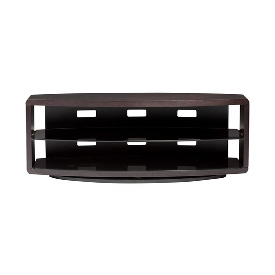
Component List
A - Phillips Screwdriver
(Not Provided)
B - 4mm Hex L-Wrench
C - Cam Fastener x 4
D - Dowel Pin x 8
E - Cam Bolt x 4
F - 1/4-20 x 38mm
Machine Screw x 6
G - M6 x 20mm
Machine Screw
Hex Drive x 8
H - M6 x 6mm
Machine Screw
Hex Drive x 8
I - Upper Bracket x 4
J - Lower Bracket x 4
K - Shelf Clip x 4
L - 5/32 x 12mm
Machine Screw x 4
Phillips Drive
M - Rubber Stem Bumper
x 6
N - Top Panel x 1
O - Side Panels x 2
P - Base Assembly x 1
Q - Back Panel x 1
R - Glass Shelves x 2
Designed by Louis A. Lara
These distinctive product configurations are protected by US and international
patents, trade dress, and/or copyright laws.
BDI are trademarks of Becker Designed, Inc.
All Rights reserved. © 2010 BDI
Made in Taiwan. 9729 Revision: 05-03-10
VALERA
9729
Valera is engineered for easy assembly. Carefully follow this procedure to
prevent any damage.
Placement and Maintenance
Valera is designed for indoor use on level floors. Clean glass with glass cleaner,
and wood veneer with a moist cloth.
Step 1
Unpack and Identify
Unpack and identify the components at left. The assembly workspace should be
a non-marring surface such as carpet. For missing hardware pieces, please
contact BDI Customer Service at customerservice@bdiusa.com. For all other
concerns, please contact your BDI Retailer.
BDIUSA.COM
O
P
R
1
ASSEMBLY INSTRUCTIONS
CUSTOMERSERVICE@BDIUSA.COM
N
O
Q
Advertisement
Table of Contents

Subscribe to Our Youtube Channel
Related Manuals for BDI VALERA 9729


Summary of Contents for BDI VALERA 9729
- Page 1 Unpack and identify the components at left. The assembly workspace should be a non-marring surface such as carpet. For missing hardware pieces, please contact BDI Customer Service at customerservice@bdiusa.com. For all other concerns, please contact your BDI Retailer. I - Upper Bracket x 4...
- Page 2 Step 2 Install Hardware onto Top Panel Lay Top Panel (N) on its Top on a carpeted surface, with holes facing up. Install Dowel Pins (D) and Cam Bolts (E) into Top Panel (N) using Phillips Screwdriver (A) . Install Upper Brackets (I) onto Top Panel (N) with Machine Screws (G) using 4mm Hex L-Wrench (B) , do not fully tighten for ease of Back Panel (Q) installation.
- Page 3 Step 5 Attach Side Panels to Top Panel Attach Side Panels (O) to Top Panel (N) by lowering Side Panels (O) onto Dowel Pins (D) and Cam Bolts (E) . Make certain shelf pin holes face inward. Tighten Cam Fasteners (C) with 4mm Hex L-Wrench (B) . Step 6 Attach Base Assembly Insert Dowel Pins (D) into Side Panels (O) .
- Page 4 Step 7 Install Back Panel Install Back Panel (Q) onto Upper Brackets (I) and Lower Brackets (J) with Machine Screws (H) using 4mm Hex L-Wrench (B) . Fasten the Machine Screws (H) in the middle of the Back Panel (Q) and then fasten the outside Machine Screws (H) .
Need help?
Do you have a question about the VALERA 9729 and is the answer not in the manual?
Questions and answers