
Related Manuals for Chauvin Arnoux AEMC 6527


Summary of Contents for Chauvin Arnoux AEMC 6527
- Page 1 All manuals and user guides at all-guides.com 6527 MEGOHMMETER E N G L I S H User Manual 1.800.561.8187 information@itm.com www. .com...
- Page 2 All manuals and user guides at all-guides.com 1.800.561.8187 information@itm.com www. .com...
- Page 3 All manuals and user guides at all-guides.com Statement of Compliance Chauvin Arnoux , Inc. d.b.a. AEMC Instruments ® ® certifies that this instrument has been calibrated using standards and instruments traceable to international standards. We guarantee that at the time of shipping your instrument has met its published specifications.
-
Page 4: Table Of Contents
All manuals and user guides at all-guides.com Table of Contents 1. INTRODUCTION ................4 1.1 International Electrical Symbols ..........5 1.2 Definition of Measurement Categories ........5 1.3 Receiving Your Shipment ............6 1.4 Ordering Information ..............6 1.4.1 Accessories and Replacement Parts ......6 2. PRODUCT FEATURES ..............7 2.1 Description ................7 2.2 Key Features ................7 2.3 Control Features ...............8 2.4 Display ..................9 2.5 Button Functions ..............10... - Page 5 All manuals and user guides at all-guides.com 4. MAINTENANCE ................23 4.1 Battery Replacement ..............23 4.2 Fuse Replacement ..............24 4.3 Cleaning ..................24 5. SPECIFICATIONS................25 5.1 Reference Conditions .............25 5.2 Specifications ................25 Limited Warranty ...................28 Warranty Repairs ...................28 Megohmmeter Model 6527 1.800.561.8187 information@itm.com www. .com...
-
Page 6: Introduction
All manuals and user guides at all-guides.com CHAPTER 1 INTRODUCTION WARNING This device complies with safety standard IEC-61010-1. (Ed 2–2001) for voltages up to 600V in category IV, at an altitude of less than 2000m, indoors, with a pollution level of not more than 2. These safety instructions are intended to ensure the safety of persons and proper operation of the device. If the tester is used other than as specified in this data sheet, the protection provided by the device may be impaired. • Do not use the instrument in an explosive atmosphere or in the presence of flammable gases or fumes. • Do not use the instrument on networks of which the voltage or category exceeds those mentioned. -
Page 7: International Electrical Symbols
All manuals and user guides at all-guides.com International Electrical Symbols Signifies that the instrument is protected by double or reinforced insulation. This symbol on the instrument indicates a WARNING that the operator must refer to the user manual for instructions before operating the instrument. In this manual, the symbol preceding instructions indicates that if the instructions are not followed, bodily injury, installation/sample and/or product damage may result. -
Page 8: Receiving Your Shipment
All manuals and user guides at all-guides.com Receiving Your Shipment Upon receiving your shipment, make sure that the contents are consis- tent with the packing list. Notify your distributor of any missing items. If the equipment appears to be damaged, file a claim immediately with the carrier and notify your distributor at once, giving a detailed description of any damage. Save the damaged packing container to substantiate your claim. Ordering Information Megohmmeter Model 6527.......... -
Page 9: Product Features
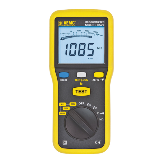
All manuals and user guides at all-guides.com CHAPTER 2 PRODUCT FEATURES Description The Model 6527 is a portable multi-range megohmmeter capable of measuring insulation resistance from 1kΩ to 4000MΩ. It has three user selectable test voltages of 250V, 500V and 1000V. The Model 6527 also features a continuity test function with audible beeper for resistances under 35Ω, and an overload protection of 600Vrms. -
Page 10: Control Features
All manuals and user guides at all-guides.com Control Features MEGOHMMETER MODEL 6527 ∞ HOLD TEST LOCK ZERO / TEST MΩ 250V 500V 1000V Figure 2-1 1. VΩ Jack / COM input jack 2. LCD Display (see § 2.4) 3. Data Hold, Test Lock and Zero/Backlight buttons (see § 2.5) 4. Rotary Function Switch (see § 2.7) Megohmmeter Model 6527 1.800.561.8187 information@itm.com www. .com... -
Page 11: Display
All manuals and user guides at all-guides.com Display ∞ Figure 2-2 Symbol Description Risk of electric shock > 25V Not used Test lock function enabled Lead compensation for resistance measurements Continuity measurement with buzzer HOLD Locking of the display Indicates the battery is low and must be replaced (see § 4.1) Giga- Mega- Kilo-... -
Page 12: Button Functions
All manuals and user guides at all-guides.com Button Functions Button Range Function • Short Press: Holds the display of the measured value. When activated, The HOLD symbol will appear and the measurement is locked. To deactivate, press the HOLD button again. HOLD Position •... -
Page 13: Range Switch Positions
All manuals and user guides at all-guides.com Function Switch Positions MΩ 250V 500V 1000V Figure 2-3 Range Function 1000V Insulation measurement at 1000V 500V Insulation measurement at 500V 250V Insulation measurement at 250V Turns the instrument OFF AC voltage measurement (V) DC voltage measurement (V) Continuity measurement with buzzer kΩ... -
Page 14: Operation
All manuals and user guides at all-guides.com CHAPTER 3 OPERATION Starting the Instrument Turn the rotary switch to the appropriate function. All segments of the display will light for a few seconds. The screen corresponding to the chosen function will then appear. The megohmmeter is now ready for measurements. -
Page 15: Spot Testing
All manuals and user guides at all-guides.com 3.3.2 Spot Testing As a general rule in spot testing, test voltage should be applied until no variation in reading is noted for 15 seconds, or applied for a fixed 60 seconds. What minimum value should be measured? The IEEE standard No. 43-1974 states that it is impossible to specify the value of insulation resistance at which a winding will fail electrically, but on motors, minimum readings generally stated are: Rated Voltage R Minimum 250 or less 2MΩ... -
Page 16: Tips For Successful Insulation Resistance Testing
All manuals and user guides at all-guides.com 3.3.4 Tips For Successful Insulation Resistance Testing • Check with the equipment manufacturer for factory insulation resistance readings. • Do not rely on insulation resistance testing alone as proof of wind- ing conditions. • Do not expect the same value for all parts of all machines. • Observe consistent test time duration, recognizing that total current through insulation under test will vary with time. • Correct all readings properly to a standard reference temperature (see IEEE Std. #43-1974, Temperature Correction Curve). - Page 17 All manuals and user guides at all-guides.com Figures 3-2 and 3-3 show the connections for testing insulation from a supply conductor to ground (e.g. a motor frame). Conductor Under Test Cable Insulation Figure 3-2 Conductor Under Test Cable Insulation Figure 3-3 Megohmmeter Model 6527 1.800.561.8187 information@itm.com www. .com...
- Page 18 All manuals and user guides at all-guides.com Figure 3-4 shows the connections to a transformer (lighting or distribution). Tested Winding Make sure that the switches and/ or circuit breakers on both sides Transformer are open. Grounding Lug Check the high voltage winding to ground, low voltage to ground, and the resistance between them with no winding grounded. Figure 3-4 Figure 3-5 shows the connections Jumpers for measuring the insulation of a three-phase line to ground by connecting the jumpers between phases.
-
Page 19: Insulation Resistance Measurements On Motors
All manuals and user guides at all-guides.com 3.3.6 Insulation Resistance Measurements on Motors Figure 3-6 shows reading the resistance to ground of a three-phase motor winding. Since the three-phase motors are internally connected, it is only necessary to connect one lead to the motor lead and the other lead to the motor frame as shown. Figure 3-6 Figure 3-7 shows the windings of a three- phase motor separated. Sometimes this can be done at the lead termi- nals, while other times the end bells must be removed to get at the lead wires of the coils. - Page 20 All manuals and user guides at all-guides.com Figure 3-8 shows connec- Motor Side of Switch: tions for testing insulation Connection to One Leg from a supply conductor in a switchbox to ground (motor frame). An identical test Starter In may be carried out from the motor starter. Grounded Motor Frame Figure 3-8 Megohmmeter Model 6527 1.800.561.8187...
-
Page 21: Measuring Mω Insulation Resistance
All manuals and user guides at all-guides.com Measuring MΩ Insulation Resistance • Turn the function switch to desired test voltage range (250V, 500V or 1000V). • Connect the black test lead to the (COM) terminal and the red one to the (VΩ) terminal. • Connect the test lead to sample under test. Warning: Do not activate the test before the leads are properly connected to the sample under test. Do not remove the test leads from the sample under test before the discharge process is completed. -
Page 22: Voltage Measurements
All manuals and user guides at all-guides.com Voltage Measurements or V • Turn the function switch to the V range, accordingly. • Connect the black test lead to the (COM) terminal and the red one to the (VΩ) terminal. • Connect to the sample under test. 600V CAT IV Figure 3-10 Megohmmeter Model 6527 1.800.561.8187 information@itm.com www. .com... -
Page 23: Continuity Measurements
All manuals and user guides at all-guides.com Continuity Measurements Warning: Tests are to be carried out on non-energized circuits only! The Model 6527 generates a 200mA current between the VΩ and COM terminals. It then measures the voltage across the two terminals and from it deduces the value of R = V/I. • Turn the function switch to • Connect the black test lead to the (COM) terminal and the red one to the (V-Ω) terminal. • Connect to the sample under test. • The megohmmeter will continue generating a test current (200mA) until it is switched out of the continuity function. Turn the megohmme- ter OFF when finished and before touching the lead ends. -
Page 24: Lead Resistance Compensation
All manuals and user guides at all-guides.com 3.6.1 Lead Resistance Compensation To set the compensation of the resistance of the measurement leads, pro- ceed as follows: • Short-circuit the black and red leads connected to the meter. • Hold the ZERO/ button down until the display unit indicates the lowest value. The symbol will display. • Release the ZERO/ button. The correction value is displayed and stored. NOTE: Valid in V , Ω and kΩ positions only Resistance Measurements The Model 6527 generates a DC voltage between the V-Ω... -
Page 25: Maintenance
All manuals and user guides at all-guides.com CHAPTER 4 MAINTENANCE WARNING: • For maintenance use only specified replacement parts. • To avoid electrical shock, do not attempt to perform any servicing unless you are qualified to do so. • To avoid electrical shock and/or damage to the instrument, do not get water or other foreign agents into the case. Turn the instrument OFF and disconnect the unit from all the circuits before opening the case. Battery Replacement WARNING: Make sure that no terminals are connected and that the switch is in the OFF position before opening the back of the instrument. -
Page 26: Fuse Replacement
All manuals and user guides at all-guides.com Fuse Replacement WARNING: Make sure that no terminals are connected and that the switch is in the OFF position before opening the back of the instrument. To replace the fuse, proceed as follows: • Set the switch to OFF. • Disconnect the measurement leads from the input terminals. • Using a screwdriver, unscrew the three screws of the battery com- partment cover located on the back of the housing. -
Page 27: Specifications
All manuals and user guides at all-guides.com CHAPTER 5 SPECIFICATIONS Reference Conditions Influence Quantity Reference Values Temperature 23°C ± 2°K Relative Humidity 45 to 75% Specifications ELECTRICAL INSULATION RESISTANCE (250V) Ω Ω Ω Ω Range 400M Ω Ω Ω Ω Resolution 0.001M 0.01M... - Page 28 All manuals and user guides at all-guides.com RESISTANCE (Ω) Range 400k Ω Resolution 0.1k Ω Accuracy 1.2% ± 3cts Overload (OL) Protection Fusible HPC; FF 0.5 A - 600V; 6.3 x 32 Short-circuit Current < 1.5mA CONTINUITY ( Ω Ω Range Ω...
- Page 29 All manuals and user guides at all-guides.com 1.800.561.8187 information@itm.com www. .com...
-
Page 30: Limited Warranty
All manuals and user guides at all-guides.com Limited Warranty The Model 6527 is warranted to the owner for a period of one year from the date of original purchase against defects in manufacture. This limited warranty is given by AEMC Instruments, not by the distributor from whom it was pur- ® chased. This warranty is void if the unit has been tampered with, abused or if the defect is related to service not performed by AEMC Instruments. ® Full warranty coverage and product registration is available on our website at www.aemc.com/warranty.html. Please print the online Warranty Coverage Information for your records. What AEMC Instruments will do: ®... - Page 31 All manuals and user guides at all-guides.com Megohmmeter Model 6527 1.800.561.8187 information@itm.com www. .com...
- Page 32 All manuals and user guides at all-guides.com 05/13 99-MAN 100363 v4 Chauvin Arnoux , Inc. d.b.a. AEMC Instruments ® ® 1.800.561.8187 information@itm.com www. .com...
Need help?
Do you have a question about the AEMC 6527 and is the answer not in the manual?
Questions and answers