
Related Manuals for Chauvin Arnoux AEMC True Megohmmeter 3528


Summary of Contents for Chauvin Arnoux AEMC True Megohmmeter 3528
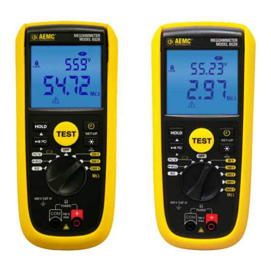
- Page 1 Megohmmeter Models 6528 and 6529 User Manual True Megohmmeter ® ENGLISH www.aemc.com...
- Page 2 No part of this documentation may be reproduced in any form or by any means (including electronic storage and retrieval or translation into any other language) without prior agreement and written consent from Chauvin Arnoux®, Inc., as governed by United States and International copyright laws. Chauvin Arnoux , Inc.
- Page 3 Statement of Compliance Chauvin Arnoux , Inc. d.b.a. AEMC Instruments certifies that this ® ® instrument has been calibrated using standards and instruments traceable to international standards. We guarantee that at the time of shipping your instrument has met its published specifications.
- Page 4 MEASUREMENT CATEGORIES Thank you for purchasing the True Megohmmeter Model 6528 or 6529. For best results ® with your instrument: ■ Read this user manual carefully ■ Respect precautions for use AC - Alternating current DC - Direct Current AC or DC Double insulated Shock Hazard Fuse...
- Page 5 PRECAUTIONS FOR USE Failure to comply with safety instructions can create a risk of electric shock, fire, explosion and destruction of the instrument or the installations. If the instrument is used other than as specified in this User Manual, the protection provided by the instrument may be impaired. ■...
-
Page 6: Table Of Contents
TABLE OF CONTENTS 1. INTRODUCTION ....................7 Receiving Your Shipment ........................7 Ordering Information .......................... 7 Accessories ............................8 Replacement Parts ..........................8 2. OVERVIEW ...................... 8 Description ............................8 Insulation Resistance Testing Principal of Operation ................. 9 Megohmmeter Models 6528 & 6529 — Front View ................9 TEST Button and Function Keys ...................... -
Page 7: Introduction
1. INTRODUCTION Receiving Your Shipment Upon receiving your shipment, make sure that the contents are consistent with the packing list. Notify your distributor of any missing items. If the equipment appears to be damaged, file a claim immediately with the carrier and notify your distributor at once, giving a detailed description of any damage. Save the damaged packing container to substantiate your claim. -
Page 8: Accessories
Accessories Continuity Probe for use with Megohmmeters and Installation Testers ....................Cat. #2138.54 Replacement Parts Pouch – replacement for Models 1026, 6528, & 6529 (7 x 8.5 x 2”) ......... Cat. #2117.73 Lead – set of (2), 5 ft silicone color-coded (red/black) with 4mm straight/right angle banana plugs (Rated 1000V CAT IV, UL) .................... -
Page 9: Insulation Resistance Testing Principal Of Operation
Insulation Resistance Testing Principal of Operation Insulation resistance measurement is based on Ohm’s Law. By applying a known DC voltage and then measuring the current flowing, the instrument can determine the value of the resistance. In principle, the value of the insulation resistance is very high, but not infinite. Therefore, by measuring the low current flowing, the instrument indicates the insulation resistance value, providing a result in kΩ, MΩ, or GΩ. -
Page 10: Test Button And Function Keys
TEST Button and Function Keys 2.4.1 TEST Button Pressing the TEST button starts an insulation measurement. It also serves to confirm a programmed threshold. • Performs battery voltage check (§3.2) • In resistance measurement, it is used to enter/exit the DMR mode and record the reference measurement (§3.7.1) •... -
Page 11: Terminals
Terminals Ω FUSED The instrument has two measurement terminals: + (positive) and COM (common). 700 V Configuration Mode Configuration mode enables you to set several options for the instrument. To open configuration mode, turn the rotary switch to OFF. Then press and hold down the SET-UP key for >2s while turning the rotary switch to any position. -
Page 12: Alarm Buzzer
Alarm Buzzer To enable/disable the audible Alarm buzzer in Insulation mode: 1. Turn the rotary switch to OFF. 2. Press and hold down the SET-UP key for >2s turning the rotary switch to any position. The LCD momentarily displays ConF to indicate the insturment is in configuration mode. symbol appears on the display. - Page 13 2.12.1 Alarm Functions The alarm functions make it possible to rapidly confirm that the readings are OK, without looking at the display. You can adjust the alarm function default settings by adjusting the thresholds. Function Default Threshold Programmable Threshold Insulation 50V* 50kΩ...
-
Page 14: Operation
3. OPERATION Battery Installation Place the batteries in the instrument as follows: 1. Use a Phillips screwdriver to remove the battery cover screw on the back of the instrument (see illustration on right). 2. Install the batteries, respecting polarity. Requires six AA (LR6) batteries. -
Page 15: Stand, Door Or Magnetic Mount
Stand, Door or Magnetic Mount For convenience, the instrument can be used in different positions: ■ With the stand - simply pull the back stand down to free it from its slot, then fold it and insert the end in the upper available slot. ■... -
Page 16: Continuity
3.5.1 Voltage Error Indicators ■ If the measurement is outside of the measurement range, the instrument displays OL. Continuity To avoid electrical shock and damage to the instrument when measuring resistance or continuity in a circuit, ensure power to the circuit is turned OFF and all capacitors are discharged. ... -
Page 17: Resistance
3.6.1 Compensation of the Measurement Leads Ω Short the input terminals by touching them together. Then press the key and hold it down for >2s. The LCD should display 0Ω. If current is 0 mA when the terminals are shorted, verify the fuse is good. NOTE: If the resistance of the leads is >5Ω, compensation is not possible. -
Page 18: Insulation Resistance Tests
4. The threshold percentage can be set from 0.1% to 399.9%; default is 5%. When finished setting the threshold percentage, press TEST to exit SET-UP mode. 5. Connect the red lead to the terminal and the black lead to the COM terminal. 6. - Page 19 The other test types are selected via the SET-UP key: DESCRIPTION Lock the TEST button. In this mode, after you start the measurement, it continues without requiring you to keep the TEST button pressed. The test will press run until you stop it, or when 40 minutes have passed. Activate timed test mode.
- Page 20 6. When performing insulation measurement, you can press the key to enable the alarm feature. If the measurement falls below the alarm threshold, the alarm will activate. To set alarm threshold (§2.12). 7. At the end of the test, either release the TEST button (for unlocked tests) or press the TEST button a second time (for tests).
- Page 21 IEEE-43 recommends that good insulation will exhibit an increase in resistance at the 10-minute point that should be at least two times greater than the measurement taken at the one-minute point. Therefore, healthy insulation will exhibit a PI ratio of 2 or higher. Newer insulation material can progress through the absorption phase very quickly and therefore display a PI ratio of 1.
- Page 22 3.8.2.3 Conducting a Dielectric Absorption Ratio (DAR) Test The dielectric absorption ratio test is typically accomplished by measuring the insulation resistance taken at the 30 second time interval and comparing it to the insulation resistance measurement at the 60 second time interval. The instrument allows user programming of both time points if necessary.
- Page 23 3.8.2.5 Performing a Timed Test 1. Turn the rotary switch to an insulation voltage setting. Choices are 250V, 500V, 1000V (available on both the Models 6528 and 6529), and 50V and 100V (available on the Model 6529 only). The test voltage to select depends on the voltage of the installation to be tested.
-
Page 24: Maintenance
4. MAINTENANCE The instrument has no parts that can be replaced by personnel who are not trained and approved. Any non-approved repair or other work, or replacement of a part by an “equivalent,” may severely compromise safety. Cleaning Periodically wipe the case with a damp cloth and mild detergent. Do not use abrasives or solvents. Dirt or moisture in the terminals can affect the readings. -
Page 25: General Specifications
5. GENERAL SPECIFICATIONS Maximum Voltage applied to terminals 700VRMS or DC Storage temperature -40 to 140°F (-40 to 60°C) Operating temperature 14 to 122°F (-10 to 50°C) Insulation 4000PPM/°C, Ohm/Cont 2%/10°C+2D, Temperature coefficient V 0.3%/10°C+D Relative humidity 10% to 90% Operating Altitude 0 to ~6500’... -
Page 26: Electrical Specifications
6. ELECTRICAL SPECIFICATIONS General Condition of Reference Influencing Quantity Conditions of Reference Ambient temperature 73.4°F ± 5.4°F (23°C ± 3°C) Relative humidity [45%; 75%] Electric field ≤ 0.1V/m AC Power supply (batteries voltage) 8 to 9V AC/DC Voltage Measurement Uncertainty Range Resolution ±(% of reading +Digits) -
Page 27: Insulation Resistance Specification
Insulation Resistance Specification Measurement range: 0.01MΩ to 10GΩ Model 6529: 50, 100, 250, 500, 1000V Test voltages: Model 6528: 250, 500, 1000V Test voltage accuracy: +25%, 0% Nominal current: Auto discharge: Discharge time 2s for C=2µF Inhibit test if terminal voltage >30V prior to initialization Live circuit detection: of test Maximum capacitive load: 2µF at nominal voltage and nominal current. -
Page 28: Repair And Calibration
CSA# on the outside of the shipping container. If the instrument is returned for calibration, we need to know if you want a standard calibration, or a calibration traceable to N.I.S.T. (Includes calibration certificate plus recorded calibration data). Ship To: Chauvin Arnoux , Inc. d.b.a. AEMC Instruments ®... -
Page 29: Limited Warranty
9. LIMITED WARRANTY The instrument is warranted to the owner for a period of two years from the date of original purchase against defects in manufacturing. This limited warranty is given by AEMC Instruments, not by the ® distributor from whom it was purchased. This warranty is void if the instrument has been tampered with, abused, or if the defect is related to service not performed by AEMC Instruments. - Page 30 NOTES: Megohmmeter Models 6528/6529...
- Page 31 NOTES: Megohmmeter Models 6528/6529...
- Page 32 10/20 99-MAN 100491 v1 Chauvin Arnoux , Inc. d.b.a. AEMC Instruments ® ® 15 Faraday Drive • Dover, NH 03820 USA Phone: (603) 749-6434 • Fax: (603) 742-2346 www.aemc.com...
Need help?
Do you have a question about the AEMC True Megohmmeter 3528 and is the answer not in the manual?
Questions and answers