
Related Manuals for Chauvin Arnoux AEMC 404


Summary of Contents for Chauvin Arnoux AEMC 404
- Page 1 User Manual ENGLISH Power Clamp-On Meter Model 404 CLAMP-ON METERS WITH AEMC INSTRUMENTS ®...
- Page 2 , Inc. has made every reasonable effort to ensure that this documentation is accurate; ® but does not warrant the accuracy or completeness of the text, graphics, or other information contained in this documentation. Chauvin Arnoux , Inc. shall not be liable for any damages, special, indirect, ®...
- Page 3 Statement of Compliance Chauvin Arnoux , Inc. d.b.a. AEMC Instruments ® ® certifies that this instrument has been calibrated using standards and instruments traceable to international standards. We guarantee that at the time of shipping your instrument has met the instrument’s published specifications.
-
Page 4: Table Of Contents
TABLE OF CONTENTS 1. INTRODUCTION...............7 1.1 INTERNATIONAL ELECTRICAL SYMBOLS ......... 7 1.2 DEFINITION OF MEASUREMENT CATEGORIES (CAT) ... 7 1.3 PRECAUTIONS FOR USE.............. 8 1.4 RECEIVING YOUR SHIPMENT ............. 9 1.5 ORDERING INFORMATION ............9 1.5.1 Accessories ..................9 1.5.2 Replacement Parts ................ 9 2. - Page 5 4.4 CONFIGURATION ................. 23 4.4.1 Configuring the Maximum Resistance for Continuity ....23 4.4.2 Auto Power OFF ................23 4.4.3 Configuring Current Threshold for True InRush Measurement.. 24 ® 4.4.4 Changing the Default Temperature Unit ........24 4.4.5 Configuring the Adapter Function Scale Factor ......25 4.4.6 Default Configuration ..............
- Page 6 5.2.9 Frequency Measurements ............38 5.2.9.1 Voltage ................38 5.2.9.2 Current ................38 5.2.10 Temperature Measurement ............39 5.2.11 Adapter Function Measurement ..........39 5.2.11.1 In DC mode ..............39 5.2.11.2 In AC mode ..............40 5.3 ENVIRONMENTAL CONDITIONS ..........40 5.4 MECHANICAL SPECIFICATIONS ..........
-
Page 7: Introduction
1. INTRODUCTION Instruments Model 404 Clamp-On Meter. Thank you for purchasing an AEMC ® For best results from your instrument and for your safety, read the enclosed operating instructions carefully and comply with the precautions for use. Only qualified and trained operators should use this product. 1.1 INTERNATIONAL ELECTRICAL SYMBOLS Signifies that the instrument is protected by double or reinforced insulation. -
Page 8: Precautions For Use
1.3 PRECAUTIONS FOR USE This device complies with safety standards IEC/EN 61010-1 or BS EN 61010-1 and IEC/EN 61010-2-032 or BS EN 61010-2-032 for voltages of 1000 V in CAT IV and 1500 V in CAT III. These safety instructions are intended to ensure the safety of persons and proper operation of the device. -
Page 9: Receiving Your Shipment
1.4 RECEIVING YOUR SHIPMENT Upon receiving your shipment, make sure that the contents are consistent with the packing list. Notify your distributor of any missing items. If the equipment appears to be damaged, file a claim immediately with the carrier and notify your distributor at once, giving a detailed description of any damage. -
Page 10: Product Features
2. PRODUCT FEATURES The Clamp-On Meter Model 404 is a 6000-count professional electrical measuring instrument that combines the following functions: ■ Current measurement ■ Measurement of Inrush current / overcurrent (True InRush ® ■ Voltage measurement ■ Frequency measurement ■ Continuity test with buzzer ■... -
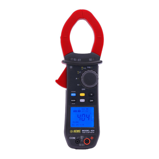
Page 11: Front & Back Of Instrument
2.1 FRONT & BACK OF INSTRUMENT Figure 1 Figure 2 Item Designation See § Jaws with centering marks (see connection 4.5 to 4.13 principles) Physical Guard Rotary Function Switch Function Buttons Backlit Display Input Terminals Trigger Battery Compartment & Compartment Screw For instructions on installing the batteries, see §... -
Page 12: Rotary Switch
2.2 ROTARY SWITCH The rotary switch has six positions. To access the , and functions, set the switch to the desired function. The functions are described in the table below. Figure 3 Item Function See § OFF mode - Turns the clamp-on Meter off AC, DC voltage measurement (V) AC, DC current measurement (A) Temperature measurement (°C/°F) -
Page 13: Function Buttons
2.3 FUNCTION BUTTONS Figure 4 Item Function See § Holds the last value on the display Zero correction A 4.9.2 Lead resistance compensation in the 4.6.1 continuity and ohmmeter functions Selects the type of measurement and configuration functions (AC, DC) Enables/disables display backlighting Enables/disables the MAX/MIN mode Enables/disables the True InRush... -
Page 14: Display
2.4 DISPLAY Figure 5 Item Function See § Mode selection display Active measurement value and unit display 4.5 to 4.13 Display of the MAX/MIN modes Type of measurement (AC or DC) Resistance measurement selection display Low battery indication Temperature unit display 4.4.4 2.4.1 Display Symbols Symbol... -
Page 15: Measurement Capacity Exceeded (Ol)
Symbol Description Hertz Ampere °C/°F Temperature unit (Celsius or Fahrenheit) Percentage Ω Milli- prefix Kilo- prefix Lead resistance compensation Continuity test Diode test Auto Power Off disabled Low battery indicator 2.4.2 Measurement Capacity Exceeded (OL) The OL (Over Load) symbol is displayed when the display capacity is exceeded. 2.5 TERMINALS Figure 6 The terminals are used as follows:... -
Page 16: Function Buttons
3. FUNCTION BUTTONS The buttons respond differently to short, long, and sustained presses. , and buttons provide additional functions and provide the detection and acquisition of parameters complementary to the basic measurements. ■ Each of these buttons can be used independently of the others or in conjunction with each other. -
Page 17: Button (Second Function)
BUTTON (SECOND FUNCTION) This button is used to select the type of measurement (AC, DC) and the second functions marked in yellow next to the relevant positions of the switch. It can also be used to modify the default values in the configuration mode (see §... -
Page 18: Max/Min Button
MAX/MIN BUTTON This button activates the detection of the MAX and MIN values of the measurements made. MAX and MIN are the extreme mean values in DC and the extreme RMS values in AC. 3.4.1 Normal Mode NOTE: In this mode, the Auto Power Off function of the device is automatically disabled. -
Page 19: The Max/Min Mode + Activation Of The Hold Mode
3.4.2 The MAX/MIN Mode + Activation of the HOLD Mode Successive presses on Function Displays the MAX/MIN values detected before the button was pressed. short When the button is pressed, the last value is held on the display. NOTE: The HOLD function does not interrupt the acquisition of new MAX/MIN values. -
Page 20: Button
BUTTON This button is used to display the frequency measurements of a signal. NOTE: This button is not functional in the DC mode. 3.5.1 Normal Mode Successive presses on Function Displays: 1. The frequency of the signal measured 2. The present voltage (V) or current (A) measurement 3.5.2 The Hz Function + Activation of the HOLD Mode Successive... -
Page 21: Button
BUTTON This button is used to display and store the reference value or to display the differential and relative value, in the unit of magnitude measured or in %. Successive presses on Function - Enters the ΔREL mode, to store, then displays the reference value. -
Page 22: Operation
4. OPERATION 4.1 INSTALLING THE BATTERIES Insert the batteries supplied with the device as follows: 1. Using a screwdriver, unscrew the battery compartment cover ( ) from the back of the housing. 2. Insert the (4) 1.5 V AA batteries supplied ( ), observing polarities. -
Page 23: Configuration
4.4 CONFIGURATION As a safety measure and to avoid repeated overloads on the inputs of the device, configuration operations should only be performed when the device is disconnected from all dangerous voltages. 4.4.1 Configuring the Maximum Resistance for Continuity To configure the maximum resistance allowed for a continuity: 1. -
Page 24: Configuring Current Threshold For True Inrush Measurement
4.4.3 Configuring Current Threshold for True InRush ® Measurement To configure the triggering current threshold of the True InRush measurement: ® 1. In the OFF position, hold the button down while turning the switch until the full screen display ends and a beep is emitted. The display will indicate the percentage overshoot to apply to the measured current to determine the measurement triggering threshold. -
Page 25: Configuring The Adapter Function Scale Factor
4.4.5 Configuring the Adapter Function Scale Factor To configure the Adapter function scale factor: 1. From the OFF position, hold the button down while turning the switch until the full screen display ends and a beep is emitted signaling the instrument is in configuration mode. The display unit indicates the stored scale factor value. -
Page 26: Voltage Measurement (V)
4.5 VOLTAGE MEASUREMENT (V) To measure voltage, proceed as follows: 1. Set the switch to 2. Connect the black lead to the COM terminal and the red lead to the terminal. 3. Connect the test probes or the alligator clips to the circuit to be measured. The device selects AC or DC automatically according to which measured value is larger. -
Page 27: Lead Resistance Compensation
4.6.1 Lead Resistance Compensation WARNING: Before the compensation is executed, the MAX/MIN and HOLD modes must be deactivated. To perform automatic compensation of the test lead resistance, proceed as follows: 1. Short-circuit the leads connected to the meter. 2. Hold the button down until the display unit indicates the lowest value. -
Page 28: Diode Test
4.8 DIODE TEST WARNING: Before performing the diode test, make sure that the circuit is off and all capacitors have been discharged. 1. Set the switch to and press the button twice. symbol is displayed. 2. Connect the black lead to the COM terminal and the red lead to the terminal. -
Page 29: Current Measurement (A)
4.9 CURRENT MEASUREMENT (A) The jaws are opened by pressing the trigger on the body of the meter. The arrow on the jaws of the clamp-on meter (see the diagram below) should point in the presumed direction of current flow, from the generator to the load. Make sure that the jaws have closed correctly after clamping around the conductor. -
Page 30: Dc Measurement
4.9.2 DC Measurement and select DC if the display does not indicate 0; the DC Set the switch to zero must first be corrected. Step 1: Correction of DC Zero NOTE: The clamp must not be closed on the conductor during the DC zero correction. -
Page 31: Starting Current Or Overcurrent (True Inrush ® ) Measurement
4.10 STARTING CURRENT OR OVERCURRENT (TRUE INRUSH ) MEASUREMENT ® To measure a starting current or overcurrent, proceed as follows: 1. Set the switch to , correct the DC zero (see § 4.9.2), then clamp the jaws around the conductor to be measured. button. -
Page 32: Frequency Measurement (A)
4. Connect the test probes or the alligator clips to the circuit to be measured. The measured value is displayed on the screen. 4.11.2 Frequency Measurement (A) button. The Hz symbol is 1. Set the switch to and press the displayed. -
Page 33: Measurement With External Sensor
4.12.2 Measurement with External Sensor The device measures the temperature using a K-thermocouple. 1. Connect the K-thermocouple to the COM and input terminals of the device observing the red and black banana plug polarity. 2. Set the switch to 3. Place the K-thermocouple on the element or environment to be measured. It must not be at a dangerous voltage. -
Page 34: Adapter Function Measurement
4.13 ADAPTER FUNCTION MEASUREMENT This function makes it possible to connect any adapter or sensor that converts a measured electrical or physical quantity into a voltage (either DC or AC). A direct, immediate reading is obtained without applying a conversion factor. The measurement is made as a voltage measurement. -
Page 35: Specifications
5. SPECIFICATIONS 5.1 REFERENCE CONDITIONS Quantities of Influence Reference Conditions Temperature (23 ± 2) °C Relative humidity (45 to 75) % Supply voltage (6.0 ± 0.5) V Frequency range of the applied signal (45 to 65) Hz Sine wave Pure Peak factor of the applied alternating signal √2 Position of the conductor in the clamp... -
Page 36: Ac Voltage Measurement
5.2.2 AC Voltage Measurement Measurement (1000 to 1200) V (0.15 to 99.99) V (100.0 to 999.9) V Range 1700 V peak Specified Measurement (0 to 1100) V / 1600 V peak Range (0.15 to 9.99) V ± (1 % R + 10 cts) Accuracy ±... -
Page 37: True Inrush ® Measurement
5.2.5 True InRush Measurement ® Measurement Range 10 A to 1000 A 10 A to 1500 A Specified Measurement (0 to 100) % of the measurement range Range Accuracy ± (5 % R + 5 cts) Resolution Specific Specifications in PEAK mode in True InRush ®... -
Page 38: Diode Test
5.2.8 Diode Test Measurement Range (0.000 to 3.199) V Specified Measurement Range (1 to 100) % of the measurement range Accuracy ± (1 % R + 10 cts) Resolution 0.001 V Measurement Current 0.55 mA Indication: junction reversed or open- OL is displayed when the measured circuit voltage >... -
Page 39: Temperature Measurement
5.2.10 Temperature Measurement Function External Temperature K-thermocouple Type of Sensor (-60.0 to +999.9) °C (+1000 to +1200) °C Measurement Range (-76.0 to +1831.8) °F (+1832 to +2192) °F Specified Measurement (1 to 100) % of the (0 to 100) % of the Range measurement range measurement range... -
Page 40: In Ac Mode
5.2.11.2 In AC mode Measurement Range (5.0 to 999.9) mV (1.00 to 9.99) V Specified Measurement (1 to 100) % of the (0 to 100) % of the Range measurement range measurement range (5.0 to 99.9) mV ± (1 % R + 10 cts) Accuracy 1 % R + 3 cts (100.0 to 999.9) mV... -
Page 41: Power Supply
5.5 POWER SUPPLY Batteries Four 1.5 V AA LR6 Battery life > 350 h (without backlighting) Auto Power Off After 10 min with no switch and/or button activity 5.6 COMPLIANCE WITH INTERNATIONAL STANDARDS Compliant with standards IEC/EN 61010-1 or Electric Safety BS EN 61010-1, IEC/EN 61010-2-032 or BS EN 61010-2-032: 1000 V CAT IV and 1500 V CAT III Electromagnetic... -
Page 42: Maintenance
6. MAINTENANCE 6.1 WARNING ■ Remove the test leads on any input before opening the case. ■ Do not operate the clamp-on meter without a battery case cover. ■ To avoid electrical shock, do not attempt to perform any servicing unless you are qualified to do so. -
Page 43: Repair And Calibration
If the instrument is returned for calibration, we need to know if you want a standard calibration or a calibration traceable to N.I.S.T. (includes calibration certificate plus recorded calibration data). Ship To: Chauvin Arnoux , Inc. d.b.a. AEMC Instruments ®... -
Page 44: Limited Warranty
CSA Form and other required paperwork along with the next steps to complete the request. Then return the instrument along with the signed CSA Form. Please write the CSA# on the outside of the shipping container. Return the instrument, postage or shipment prepaid to: Chauvin Arnoux , Inc. d.b.a. AEMC Instruments ®... - Page 45 NOTES:...
- Page 46 NOTES:...
- Page 47 NOTES:...
- Page 48 99-MAN 100584 v00 AEMC Instruments ® 15 Faraday Drive • Dover, NH 03820 USA Phone: +1 (603) 749-6434 • +1 (800) 343-1391 • Fax: +1 (603) 742-2346 www.aemc.com © 2024 Chauvin Arnoux , Inc. d.b.a. AEMC Instruments. All Rights Reserved. ® ®...
Need help?
Do you have a question about the AEMC 404 and is the answer not in the manual?
Questions and answers