
Related Manuals for Chauvin Arnoux AEMC 1035


Summary of Contents for Chauvin Arnoux AEMC 1035
- Page 1 User Manual ENGLISH Megohmmeters Models 1035 & 1039 DIGITAL ANALOG MEGOHMMETERS WITH AEMC INSTRUMENTS ®...
- Page 2 15 Faraday Drive • Dover, NH 03820 USA Tel: (800) 945-2362 or (603) 749-6434 • Fax: (603) 742-2346 This documentation is provided “as is,” without warranty of any kind, express, implied, or otherwise. Chauvin Arnoux ® Inc. has made every reasonable effort to ensure that this documentation is accurate; but does not warrant the accuracy or completeness of the text, graphics, or other information contained in this documentation.
- Page 3 Statement of Compliance Chauvin Arnoux , Inc. d.b.a. AEMC Instruments ® ® certifies that this instrument has been calibrated using standards and instruments traceable to international standards. We guarantee that at the time of shipping your instrument has met its published specifications.
-
Page 4: Table Of Contents
Contents INTRODUCTION ................6 1.1 International Electrical Symbols ..........7 1.2 Definition of Measurement Categories (CAT) ......7 1.3 Receiving Your Shipment ............7 1.4 Ordering Information ..............8 1.4.1 Accessories and Replacement Parts ......8 PRODUCT FEATURES ..............9 2.1 Description ................9 2.2 Model 1035 Control Features ..........10 2.3 Model 1039 Control Features .......... - Page 5 2.7.6 Alarm Setpoints ............20 2.7.7 Relative Measurements ( REL) .......22 2.7.8 Programming the Capacitance per Unit Length (1039) ..22 SPECIFICATIONS ..............23 3.1 Electrical Specifications ............23 3.1.1 Voltage ................23 3.1.2 Insulation ..............24 3.1.3 Resistance ..............24 3.1.4 Capacitance (1039) ............25 3.1.5 Distance (1039) ............25 3.1.6 AC/DC Current (1039) ..........25...
-
Page 6: Introduction
CHAPTER 1 INTRODUCTION Warning These safety warnings are provided to ensure the safety of personnel and proper operation of the instrument. • Read the instruction manual completely and follow all safety information before operating this instrument. • Safety is the responsibility of the operator! •... -
Page 7: International Electrical Symbols
International Electrical Symbols This symbol signifies that the instrument is protected by double or reinforced insulation. This symbol on the instrument indicates a WARNING and that the operator must refer to the user manual for instructions before operating the instrument. In this manual, the symbol preceding instructions indicates that if the instructions are not followed, bodily injury, installation/sample and product damage may result. -
Page 8: Ordering Information
Ordering Information Model 1035 ....... Cat. #2116.90 (Discontinued - No longer available) Includes soft carrying case, 3 color-coded leads, 1 black test probe, 3 alligator clips, 2 grip probes, batteries and user manual......Cat. #2116.91 Model 1039 (Discontinued - No longer available) Includes soft carrying case, 2 color-coded leads, 1 black test probe, 2 alligator clips, 2 grip probes, batteries and user manual. -
Page 9: Product Features
CHAPTER 2 PRODUCT FEATURES Description These portable megohmmeters function with batteries. They can be used to check insulation and voltages, and to measure resistances. The Model 1039 can also be used for: • measurement of the capacitance of a telephone line •... -
Page 10: Model 1035 Control Features
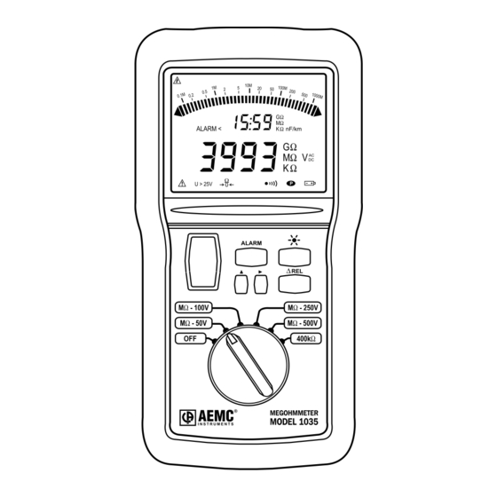
Model 1035 Control Features Figure 1 1. Safety terminals - Ø 4 mm (marked “+” and “G”) and a 3-Point socket for connecting the remote control 2. Backlight liquid crystal display 3. Buttons: Yellow (to activate insulation measurement) ALARM, and ΔREL (see § 2.7) 4. -
Page 11: Model 1039 Control Features
Model 1039 Control Features Figure 2 1. Safety terminals - Ø 4 mm (marked “mA”, “+” and “-”). Next to the “-” terminal, there are two additional contacts for connecting the remote control probe (3-Point connector). 2. Backlight liquid crystal display 3. -
Page 12: Lcd Display Symbols
LCD Display Symbols 2.4.1 Digital Display Symbols Timer On ALARM Alarm On > High Limit Trigger < Low Limit Trigger Test Voltage On – Negative Value Refer to User Manual Fuse Open >25V Measured Voltage >25 V Lead, Resistance Zeroing Active Buzzer Permanent Run –... -
Page 13: Button Functions
Button Functions 2.5.1 Yellow Push Button The yellow button is used to initiate the test voltage when measuring insulation resistance. In any function setting (except OFF), the megohmmeter is in the voltage mode and works as a voltmeter to detect if any voltage is present on the tested sample. -
Page 14: Scroll Cursor Button
2.5.4 Scroll Cursor Button When programming the alarm setpoints, the ▲ button is used to scroll through the possible values for each parameter, which flashes: MΩ or GΩ for insulation, kΩ or Ω for resistance, for the measurement units, 1,2, 3 or _ for the thousands digit, 0, 1, 2, 3, 4, 5, 6, 7, 8 and 9 for the hundreds, tens and units, “-.- - -”... -
Page 15: Measurement Functions
Measurement Functions 2.6.1 AC/DC Voltage Measurement - Safety Check As soon as the switch is set to one of the MΩ positions, the instrument measures the voltage between its + and - terminals. The value of this voltage is displayed (0 to 600 V max). -
Page 16: Resistance
The instrument indicates if the value measured is outside its measurement range. If the measured insulation resistance is greater than 400MΩ (1039), 2 or 20 GΩ (1035), the OL symbol is displayed on the digital display instead of a value. When the measurement is greater than 1.1 GΩ, the ►... -
Page 17: Capacitance (1039)
2.6.4 Capacitance (1039) Capacitance measurement corresponds to the 4000 nF position of the switch. The measurement is shown on the display accompanied by the nF symbol. The length of the telephone line measured is indicated in km on the digital threshold display, according to the programmed capacitance per unit length. -
Page 18: Ac/Dc Current (1039)
2.6.5 AC/DC Current (1039) Current measurement corresponds to the 400 mA position of the switch. The measurement is shown on the display accompanied by the mA symbol. The fuse is checked periodically. If the current measurement is greater than 400 mA , the AC/DC OL symbol is displayed on the display. -
Page 19: Battery Auto Test
DISABLING/ENABLING THE AUTO-OFF • To disable the Auto-Off, keep the button pressed down when turning ON the instrument. The symbol is then displayed, indi- cating that the Auto-Off function has been disabled. • To enable the Auto-off function, turn the instrument OFF and then turn it back ON again. -
Page 20: Alarm Setpoints
THE DIFFERENT SOUNDS When the symbol is displayed, the buzzer is active. It gives out different sounds, depending on the operation or warning. Short buzz (65 ms at 2 kHz): • - push on a button - auto OFF • Continuous buzz (at 2 kHz): - measurement is lower than the minimum setpoint - measurement is higher than the maximum setpoint... - Page 21 At this moment, it is possible to program the threshold using the ► and ▲ buttons. During this programming, if you change the switch position, you lose what you have just done. You can quit the programming mode and record the threshold by another long press on the ALARM button.
-
Page 22: Relative Measurements ( Rel)
TRIGGERING OF THE ALARM Examples in insulation measurement: • If an upper setpoint of 100 MΩ is active, the display indicates “ALARM > 100.0 MΩ”. • If the measurement exceeds this value, a continuous beep will be triggered and the whole digital threshold display will flash. •... -
Page 23: Specifications
CHAPTER 3 SPECIFICATIONS Electrical Specifications These megohmmeters display the measurement every 400 ms, which corresponds to 2.5 measurements per second for the digital display. The bargraph is refreshed every 100 ms. The digital measurement is smoothed, while the bargraph always indicates the instantaneous measurement. -
Page 24: Insulation
3.1.2 Insulation Measurement Range: Model 1039: 50 V 10 kΩ to 400 MΩ 100 V 20 kΩ to 400 MΩ Model 1035: 50 V 10 kΩ to 2 GΩ 100 V 20 kΩ to 2 GΩ 250 V 50 kΩ to 20 GΩ 500 V 100 kΩ... -
Page 25: Capacitance (1039)
3.1.4 Capacitance (1039) Measurement Range: 0 to 4000nF Range 0.00 to 399.9 nF 400 to 3999 nF Resolution 0.1 nF 1 nF Accuracy ±3 % ± 2 cts ±3 % ± 1 ct Measurement Current 1 mA 100 µA 3.1.5 Distance (1039) Measurement Range: 0 to 80 km Range 0.000 to 3.999 km... -
Page 26: Power Supply
3.1.8 Power Supply Instrument is powered by 6 x 1.5 V AA alkaline batteries, type NEDA 15 A or LR6. Measurement Consumption* Average Battery Life Voltmeter (1039/1035) 57,600 5-second Ammeter 25 mA (1039) measurements Capacitance Meter (1039) 28,800 5-second Resistance 50 mA (1039/1035) measurements... -
Page 27: Safety Specifications
Influencing Parameters Measurement Variations Influence Range Parameter Typical Maximum Temperature (-10 to +55) °C 1 % R ±1 ct / 10 °C 2 % R ±2 cts / 10 °C Relative Humidity (20 to 80) % RH 1 % R ± 2 cts 3 % R ±... -
Page 28: Operation
CHAPTER 4 OPERATION Operation Turn the rotary switch to the measurement to be performed. Connect the instrument to the sample to be tested. The units and the range are automatically selected for the best reading. The megohmmeter may be shut down manually by turning the switch to OFF. -
Page 29: Resistance Measurement
• To measure high insulation values (> 1 GΩ), you are advised to use the “G” guard terminal to remove the influence of superficial leak currents and a hands free carrying case. In this case, it is preferable to use alligator clips or wire grips rather than touch prods held in the hand. -
Page 30: Ac/Dc Current Measurement (1039)
AC/DC Current Measurement (1039) • Turn the megohmmeter ON by setting the switch to 400 mA. • Connect the leads from the mA and - terminals to the measurement points. • Record the current value displayed. Connecting the MN211 current probe accessory to the mA Amp terminals will extend the measurement range to 200 A AC Voltage Measurement (1039) •... -
Page 31: Application Examples
Application Examples 4.7.1 Insulation Measurements on Installations Ground Rod and Clamp Contact Resistance Between Rod and Soil Concentric Shells of Earth Figure 3 4.7.2 Insulation Measurements on Cables 1 1/4 1 1/2 1 3/4 Rod Diameter (inches) Figure 4 Digital Analog Megohmmeter Models 1035/1039... -
Page 32: Insulation Measurements On Motors
4.7.3 Insulation Measurements on Motors 1" dia. 1/2" dia. Figure 5 35 40 Driven Depth in Feet Ground Resistance Versus Ground Rod Depth Curve 1 Curve 2 Figure 6 Digital Analog Megohmmeter Models 1035/1039... -
Page 33: Maintenance
CHAPTER 5 MAINTENANCE Use only factory specified spare parts. The manufacturer will not be held responsible for any accident, incident, or malfunction following a repair done other than by its Service Center or by an approved repair center. Battery Replacement Before any measurements, make sure that the symbol is not displayed when a measurement function is selected. -
Page 34: Repair And Calibration
If the instrument is returned for calibration, we need to know if you want a standard calibration or a calibration traceable to N.I.S.T. (includes calibration certificate plus recorded calibration data). Ship To: Chauvin Arnoux , Inc. d.b.a. AEMC Instruments ®... -
Page 35: Limited Warranty
Then return the instrument along with the signed CSA Form. Please write the CSA# on the outside of the shipping container. Return the instrument, postage or shipment pre-paid to: Chauvin Arnoux , Inc. d.b.a. AEMC Instruments ®... - Page 36 05/23 99-MAN 100222 v18 AEMC Instruments ® 15 Faraday Drive • Dover, NH 03820 USA Phone: (603) 749-6434 • (800) 343-1391 • Fax: (603) 742-2346 www.aemc.com © Chauvin Arnoux , Inc. d.b.a. AEMC Instruments. All Rights Reserved. ® ®...
Need help?
Do you have a question about the AEMC 1035 and is the answer not in the manual?
Questions and answers