
Related Manuals for Stephill SSD6000


Summary of Contents for Stephill SSD6000
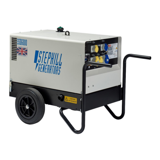
- Page 1 Issue 8 SSD6000 – SSD6000S – SE6000D4 – SSD6000/3PH 6kVA Super Silent Diesel Generators Handbook & Operation Manual +44 (0) 1933 677911 www.stephill-generators.co.uk...
-
Page 2: Table Of Contents
SSD6000 - SSD6000S - SE6000D4 Contents 3 Introduction 11 Safety Considerations - cont. 12 Battery Acid 3 Warranty Statement 12 Fire 12 Hot Parts 3 Amendments 12 Long Term Storage 4 Identification 13 Operating Instructions 13 Pre-starts Checks 4 Specification... - Page 3 SSD6000 - SSD6000S - SE6000D4 18 Fault Finding 18 Before Fault Finding 19 Basic Trouble Shooting - Key Switch Type 20 Fault Finding - Key Switch Type 21 Fault Finding - DSE 3110 23 Battery Charge System Fault Finding 24 Battery Charge Fault - Key Switch Type...
-
Page 4: Introduction
No warranty claim will be considered by Stephill Generators Ltd unless any defective parts are available for inspection by us, or our nominees, to determine the reason or cause of failure, and Stephill Generators Ltd is given the option of repair or replacement. -
Page 5: Identification
SSD6000-SSD6000S-SE6000D4 Identification Each Stephill generator will have a Serial/Data plate fitted to the set. In most cases this can be found on the control/socket panel. Below is an example of the Serial/Data plate. Fig.1 Item No. Description Generator model type AC voltage output(s) Standby rated power, kVA &... -
Page 6: Ac Output Protection Se6000D4/Ssd6000/Ssd6000S
SSD6000-SSD6000S-SE6000D4 AC Output & Protection - SE6000D4/SSD6000/SSD6000S Main alternator overload protected by double pole MCB. 115V - Thermal reset button overload protection for each individual socket. 230V - RCD protection & thermal reset button overload protection for each individual socket. -
Page 7: Control Panel Identification
SSD6000-SSD6000S-SE6000D4 Control Panel Identification Dual Voltage - Standard Fig.2 below shows a typical example of a standard dual voltage control panel. Fig.2 Item No. Description Item No. Description Hours Run Meter Serial Data Plate 230V RCD Main 20A MCB 115V Socket Outlets (Yellow) -
Page 8: 3 Phase - Standard
SSD6000-SSD6000S-SE6000D4 3 Phase - Standard Fig.4 below shows a typical example of a standard 3 Phase control panel. Fig.4 Item No. Description Item No. Description Hours Run Meter RCBO - 4 pole 230V 1Ph Socket Outlet (Blue) Earth Stud - M8 Key Switch &... -
Page 9: Generator Safety
SSD6000-SSD6000S-SE6000D4 Generator Safety Before using this equipment and to avoid personal injury, all warnings shown on the machine should be observed. The warning signage should be checked for legibility and any that have become damaged should be replaced. Carefully read and understand the instructions provided. If there is anything you do not understand DO NOT attempt to use this generator. - Page 10 SSD6000-SSD6000S-SE6000D4 Fig.6 can be found inside the canopy near the silencer on the air intake/battery box. Fig.6 Fig.7 can be found on the canopy roof near the lifting handle. Fig.7 Fig.8 below can be found on the control panel. Fig.8 A - Exhaust fumes are extremely dangerous and can kill, ensure there is adequate ventilation for clean air into the generator and exhausted air to escape.
-
Page 11: Personal Safety
The standard reference condition for total barometric pressure is 1 bar. This corresponds to an altitude of approximately 100m. Above 100m the rated power must be reduced. Flammable Environment Stephill generators must not be used in a flammable environment. Saline Environment Operation of the machine in a saline environment will require additional corrosion protection. -
Page 12: Safety Considerations
Earth Connection All Stephill products are fitted with an earth stud on the control panel this must be connected to an earthing system or spike. Any earth spike required is dependant on the local conditions of use. The size is determined... -
Page 13: Fumes
There is a risk of burns or serious mechanical injury. Long Term Storage For storage or long periods of inactivity, Stephill Generators recommend the following: Generators should be stored with oil filled to the correct capacity; Storage periods of 18 months and over may require special lubricants and treatments. -
Page 14: Operating Instructions
SSD6000-SSD6000S-SE6000D4 Operating Instructions STEPHILL GENERATORS LTD STRESS THAT THE ULTIMATE RESPONSIBILTY FOR THE SAFE USE OF THE GENERATOR RESTS WITH THE USER. Pre-start Checks Before any attempt to start the generator please follow these important guidelines. Check Oil Level - How to It is recommended to check the oil level BEFORE EVERY START OPERATION - Ref. -
Page 15: Check Fuel Level
SSD6000-SSD6000S-SE6000D4 Check Fuel Level Ensure there is enough fuel in the fuel tank. All the generator models in this handbook have a "Low Fuel Level" switch. When you turn the key switch to the first position "RUN" and the red "Low Fuel Level" LED is illuminated, this would indicate that there not enough fuel in the fuel tank and the generator will not be able to be started. -
Page 16: Key Switch - Starting Operation
SSD6000-SSD6000S-SE6000D4 Key Switch - Starting Operation Turn the key to the RUN position. The BATTERY and the LOW OIL PRESSURE red LED's will illuminate - Fig.11. If any other LED's are illuminated see the Basic Trouble Shooting-Key Switch section in this handbook. -
Page 17: Dse 3110 - Manual Start
SSD6000-SSD6000S-SE6000D4 DSE 3110 - Manual Start Once all the pre-start checks have been made you can then start the generator. Follow the procedure below: Press the button until the is displayed on the LCD screen. A red LED flashes above the button. -
Page 18: Automatic Start Operation
SSD6000-SSD6000S-SE6000D4 2-Wire Remote and ATS Auto Start/Stop Connection Location Behind the control panel there is a small push-on connector block for the remote and auto start/stop connections - Fig.13. Refer to the DC wiring diagram in this handbook for the relative terminal positions. -
Page 19: Starting Sequence
Live terminals while the generator is running! All checks and tests should only be carried out by a competent engineer. Reference wiring diagram(s) in this handbook - The diagrams will correct as to the time of printing. Stephill reserve the right to change the wiring diagrams without prior warning. -
Page 20: Basic Trouble Shooting - Key Switch Type
SSD6000-SSD6000S-SE6000D4 Basic Trouble Shooting - Key Switch Type Fault Description Checks & Tests Lamps ● Check the engine oil level. LOW OIL PRESSURE ● Check the correct engine oil has been used. The starter motor cranks when the key is in ●... -
Page 21: Fault Finding - Key Switch Type
SSD6000-SSD6000S-SE6000D4 Fault Finding - Key Switch Type Fault Possible Cause Check ● Check the battery voltage, should be around Battery 12.5V DC - Charge or Replace. ● Check the condition of the battery leads. If the battery needs charging or replacing, check the battery is being charged when the generator is running - See - Battery Charge System Fault Finding. -
Page 22: Fault Finding - Dse 3110
SSD6000-SSD6000S-SE6000D4 Fault Finding - DSE 3110 Most common faults can be Identified by the fault icon displayed on the right hand side of the LCD screen. The table below shows a fault description and/or the relevant icon together with a possible cause and checks related to the fault icon displayed. - Page 23 SSD6000-SSD6000S-SE6000D4 Fault Icon Possible Cause Check ● Check if the emergency stop button has been activated. Emergency Stop Button ● Check the switches function and wiring on the back of the emergency stop. Emergency Stop ● Check that all the green plugs are fitted DSE 3110 Control Module correctly and the wiring.
-
Page 24: Battery Charge System Fault Finding
SSD6000-SSD6000S-SE6000D4 Fault Icon Possible Cause Check ● Check oil level and top-up to the correct level Low Oil Level if necessary. ● Check the oil pressure switch operation - Switch normally closed when engine is at rest Oil Pressure Switch... -
Page 25: Battery Charge Fault - Key Switch Type
SSD6000-SSD6000S-SE6000D4 Battery Leads Check the condition of the battery terminals and the connections on the starter motor (positive) and the engine (negative). The leads should be flexible, if they feel stiff/rigid replace. Charge Regulator Location The charge regulator can be found inside the canopy roof below the control panel. Access is made by lifting the canopy roof up and leaning into the generator towards the control panel end. -
Page 26: Battery Charge Fault - Dse 3110 Type
SSD6000-SSD6000S-SE6000D4 If all the above seem to be ok then this could possibly indicate that the charge regulator has failed and would need replacing. Battery Charge Fault - DSE 3110 Type Reference will be made using the DSE 3110 DC wiring diagram contained within this handbook. -
Page 27: Fuel System Bleeding Procedure
Be aware of the generator model type below as there are different methods to bleed the fuel system. SSD6000 - SSD6000S - SSD6000/3PH These generator model types have an easy bleed fuel system with the aid of a low pressure 12V fuel pump. -
Page 28: Service And Maintenance
Alternator Service Brushless alternators employed on Stephill Generators are maintenance free. Brushed alternators, like the 3 Phase model, will require maintenance. The alternator handbook supplied with the generator will contain a maintenance chart. -
Page 29: Spares
STEPHILL GENERATORS LTD STRESS THAT THE ULTIMATE RESPONSIBILTY FOR THE SAFE USE OF THE GENERATOR RESTS WITH THE USER. Spares Engine Consumable Service Spares Basic Yanmar engine service kits are available form Stephill Generators, below are the individual parts complete with part numbers. Description Part No. -
Page 30: Control Panel - Dc Components - Standard Key Start
022-1012 Wheel 027-0022 Fuel Tank - SSD6000(S/3PH) 022-0579 Wheel Cap 027-0023 Fuel Tank - SE6000D4 022-0562 Flush Pull Handle (Roof) - SSD6000(S/3PH) 022-1033 50mm Fuel Tank Gasket 022-1003 Flush Pull Handle (Roof) - SE6000D4 014-1004 Low Fuel Switch 022-1015 Handle/Foot - Tubular - SSD6000(S/3PH) - Page 31 SE6000D4 Battery clamp bottom 022-0571 SE6000D4 Battery clamp top 022-0546 SE6000D4 Battery door 027-0022 Wheel 027-0023 Wheel cap Drawing Number Description STEPHILL GENERATORS Issue Date Revision Colour 22-696 THIRD SE6000D4 NSM Exploded view New drawing 04/02/13 Phone : +44 (0)1933 677911...
- Page 32 022-0562 SE6000D4 Fuel tank 022-0544 SE6000D4 Fuel tank mounting bracket small 022-1012 Kelch cap 022-0119 SE6000D4 Fuel tank sealing gasket Drawing Number Description Issue Date Revision STEPHILL GENERATORS THIRD 22-590 SE6000D4 Roof exploded view 08/11/04 New drawing Phone 01933 677911 ANGLE 26/05/06 New part numbers added.
- Page 33 027-0023 Wheel cap 022-0704 SSD6000 Handle 022-0724 SSD6000 Handle Lighting tower 022-0614 SSD6000 Fan cowl 022-0538 SSD6000 Engine mounting bracket 022-0697 SSD6000 NSM Alternator air inlet duct 022-0660 022-0609 SSD6000 Lift beam 022-0677 SSD6000S Lift beam 022-1055 Gas strut Drawing Number...
- Page 34 Dual voltage control panel Drawing Number Description Issue Date Revision Colour STEPHILL GENERATORS 22-665 THIRD New drawing SSD6000 & SSD6000S Roof exploded view 15/04/08 Phone : +44 (0)1933 677911 ANGLE Drawn 17/06/15 Descriptions updated. Material PROJECTION +44 (0)1933 677916 11/06/18 Fuel tank &...
- Page 38 Stephill Generators Ltd. Wallis Close, Park Farm South, Wellingborough, Northants, NN8 6AG. Copyright 2022 © Stephill Generators Ltd...
Need help?
Do you have a question about the SSD6000 and is the answer not in the manual?
Questions and answers
battery not charging
The battery on the Stephill SSD6000 may not be charging due to one or more of the following reasons:
1. The battery is flat or faulty. Measure the DC voltage at the battery while the generator is off; it should be about 12.5V. Test and replace the battery if needed.
2. The charging system is not working properly. When the generator is running, the DC voltage at the battery should be between 13.5V and 14V. If not, the charging system may be faulty.
3. There could be loose, broken, or burnt wiring between the control panel and charging components. Inspect the wiring carefully.
4. The battery charge lamp on the control panel should illuminate if there is a charging fault. If it is lit during operation, it indicates a problem.
Check all related components and connections to identify and fix the fault.
This answer is automatically generated