
Related Manuals for Stephill SSD10000S


Summary of Contents for Stephill SSD10000S
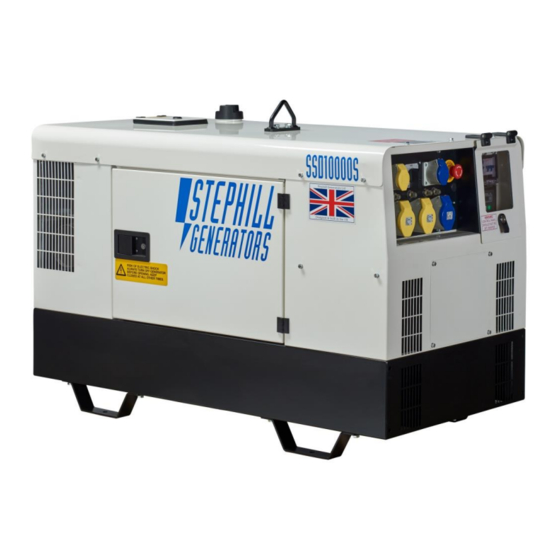
- Page 1 Issue 4 SSD10000S – SSD10000S/3PH 10.0kVA 3000rpm Generators Handbook & Operation Manual +44 (0) 1933 677911 www.stephill-generators.co.uk...
-
Page 2: Table Of Contents
4 Identification 14 Check Fuel Level 14 Control Panel Checks 5 Specification 15 Starting the Generator - Quick Start 5 AC Output Protection - SSD10000S Guide 5 AC Output Protection - SSD10000S/3Ph 5 AC Output Earthing Method 15 Manual Start... - Page 3 27 Pre-towing/Hitch Up 27 Hitching Method 28 Spares 28 Kubota Consumable Service Spares 28 Control Panel - AC Components - SSD10000S 29 Control Panel - AC Components - SSD10000S/3Ph 29 Control Panel - DC Components 29 General Spares 29 Engine Accessories Spares...
-
Page 4: Introduction
No warranty claim will be considered by Stephill Generators Ltd unless any defective parts are available for inspection by us, or our nominees, to determine the reason or cause of failure, and Stephill Generators Ltd is given the option of repair or replacement. -
Page 5: Identification
SSD10000S - SSD10000S/3PH Identification Each Stephill generator will have a Serial/Data plate fitted to the set. In most cases this can be found on the canopy roof of a SSD10000S. Below is an example of the Serial/Data plate. Fig.1 Item No. -
Page 6: Specification
ISO 8528-1 under the agreed operating conditions with the maintenance intervals and procedures being carried out as prescribed by the manufacturers. AC Output & Protection - SSD10000S Main alternator 115/230V AC outputs protected by double pole MCB. 115V - Floating Earth - Thermal reset button overload protection for each socket. -
Page 7: Engine
SSD10000S - SSD10000S/3PH Engine Type Kubota D722-E4B EU Stage V Emissions Certification Cylinders Water Cooled Cooling 719cc Displacement 3000 Net Intermittent Net Engine Power Continuous 10.3kWm AC Alternator SSD10000S SSD10000S/3PH NSM C112 SB NSM Z100 LB Type Dimensions & Weights... -
Page 8: Control Panel Identification
SSD10000S - SSD10000S/3PH Control Panel Identification SSD10000S Fig.2 Item No. Description AC Voltage Switch Emergency Stop Fuel Gauge Main MCB & 230V RCD 115V Socket Outlets (Yellow) Socket Outlet Reset Button(s) 230v Socket Outlets (Blue) Earth Stud Fuel Pump Prime Button... -
Page 9: Generator Safety
SSD10000S - SSD10000S/3PH Generator Safety Before using this equipment and to avoid personal injury, all warnings shown on the machine should be observed. The warning signage should be checked for legibility and any that have become damaged should be replaced. -
Page 10: Personal Safety
SSD10000S - SSD10000S/3PH f) Located on the control panel door/cover. g) Located on the canopy roof near the control panel. Personal Safety • Do not climb on the generator - dents may cause overheating of the acoustic lining. • Do not cover the generator as this can obstruct air inlet and outlets on the canopy which can cause the generator to overheat and cause permanent damage.. -
Page 11: Reference Relative Humidity
The standard reference condition for total barometric pressure is 1 bar. This corresponds to an altitude of approximately 100m. Above 100m the rated power must be reduced. Flammable Environment Stephill generators must not be used in a flammable environment. Saline Environment Operation of the machine in a saline environment will require additional corrosion protection. -
Page 12: Earth Connections
Earth Connection All Stephill products are fitted with an earth stud on the control panel this must be connected to an earthing system or spike. Any earth spike required is dependant on the local conditions of use. The size is determined by reference to current IEE regulations or to a competent electrician. -
Page 13: Operating Instructions
SSD10000S - SSD10000S/3PH Operating Instructions STEPHILL GENERATORS LTD STRESS THAT THE ULTIMATE RESPONSIBILTY FOR THE SAFE USE OF THE GENERATOR RESTS WITH THE USER. Pre-start Checks Before any attempt to start the generator please follow these important guidelines. Check Battery Isolator Key - Location The 12V battery supply has been fitted with a red "Battery Isolator Key". -
Page 14: Check Oil Level - How To
● Remove the oil level gauge, wipe it clean and reinstall it. ● Take the oil level gauge out again, and check the oil level. Fig.5 shows the oil fill and oil dipstick locations for the Kubota D722 engine used on the Stephill SSD10000S generators. -
Page 15: Check Coolant Level
SSD10000S - SSD10000S/3PH Check Coolant Level It is recommended to check the water/coolant level of the radiator BEFORE EVERY START OPERATION - Ref. Fig.6. The radiator is provided with a recovery tank (expansion vessel) , check the water/coolant is between the "FULL"... -
Page 16: Starting The Generator - Quick Start Guide
SSD10000S - SSD10000S/3PH Starting the Generator - Quick Start Guide This is a quick start guide , refer to the DSE 3110 Control Module - Overview within this handbook for an in- depth view/use of the DSE 3110 control module. -
Page 17: Dse 3110 Control Module - Overview
SSD10000S - SSD10000S/3PH 2-Wire Remote and ATS Auto Start/Stop Connection Location Behind the control panel there is a small push-on connector block for the remote and auto start/stop connections. Refer to the DC wiring diagram at the back of this handbook or corresponding ATS handbook for the relative terminal positions. -
Page 18: Starting Sequence
SSD10000S - SSD10000S/3PH Starting Sequence Once a start request is made the DSE 3110 will energise the pre-heat relay over a period of 10 seconds. Then the DSE 3110 will then attempt to crank the engine by operating the starter motor relay and also the fuel pump relay. -
Page 19: Waiting In Auto Mode
SAFE USE OF THE GENERATOR RESTS WITH THE USER. Monitoring Systems All standard Stephill SSD10000S generators use a DSE 3110 control module to operate/monitor the engine and generator. Most common faults/issues can be Identified by the fault icon displayed on the DSE 3110 LCD screen. The table below shows a fault icon and/or the relevant possible causes and checks. - Page 20 SSD10000S - SSD10000S/3PH Fault Icon Possible Cause Check ● Check the 40A fuse on the engine loom - Ref. wiring Fuse diagram. ● Check the plugs on the back of DSE 3110. DSE 3110 Control Module ● Check for battery + output at No.4 (starter motor relay feed) after the pre-heat time - Ref.
- Page 21 SSD10000S - SSD10000S/3PH Fault Icon Possible Cause Check The DSE 3110 is displaying the correct no-load frequency (approx. 52.5Hz) but the generator shuts down with the Low AC Voltage shutdown icon is displayed only. Capacitor ● Test and/or replace the AC alternator capacitor.
- Page 22 SSD10000S - SSD10000S/3PH Fault Icon Possible Cause Check A High Engine Temperature shutdown could be for two main reasons, either the engine has overheated or the temperature switch or wiring is faulty. ● Check the level of the water and antifreeze level - fill with...
-
Page 23: Fault Finding - General
SSD10000S - SSD10000S/3PH Fault Finding - General Fault Description Checks/Causes ● Check/test the main MCB, RCD & Reset Buttons. GENERATOR STARTS & RUNS BUT WILL NOT TAKE ● Check/test the voltage selector switch. LOAD ● Check the wiring behind the control panel. -
Page 24: Battery Charge Fault Finding Guide
SSD10000S - SSD10000S/3PH Battery Charge Fault Finding Guide Reference will be made using the DSE 3110 DC wiring diagram contained within this handbook. Normal Operation The DC voltage measured directly at the battery while the generator is at standstill should be around 12.6V Start the generator. - Page 25 SSD10000S - SSD10000S/3PH Check Charge Regulator Connections The Charge Regulator is housed behind the socket/control panel box section - Fig.11 & Fig.12. Reference the DC wiring diagram for connections. • Ensure there is continuity between the body of the charge regulator and an earth point on the engine.
-
Page 26: Service And Maintenance
Do not service or work on generator whilst the engine is running. Always disconnect battery prior to working on engine or alternator. STEPHILL GENERATORS LTD STRESS THAT THE ULTIMATE RESPONSIBILTY FOR THE SAFE USE OF THE GENERATOR RESTS WITH THE USER. -
Page 27: Trolley Kit
SSD10000S - SSD10000S/3PH Trolley Kit The Stephill SSD10000S generator has a two wheel trolley option for easy transportation. The handles also fold away for storage and protection from damage while in use. Wheels Check the tyre pressure regularly. Incorrect tyre pressure can lead to excessive wear and loss of grip. -
Page 28: Safety Precautions
The UK industry standard size number plate is 520 mm × 111 mm (20½" × 4⅜"). Hitch Type The SSD10000S generators use a standard ball hitch on the trailers. Pre-Towing/Hitch-up Follow the checks below when hitching the generator to a vehicle and before every journey. -
Page 29: Spares
STEPHILL GENERATORS LTD STRESS THAT THE ULTIMATE RESPONSIBILTY FOR THE SAFE USE, SERVICE AND CONDITION OF THE TRAILER IS WITH THE OWNER/USER. Spares Kubota Consumable Service Spares Basic Kubota engines service kits are available form Stephill Generators, below are the individual parts complete with part numbers. Description Part No. -
Page 30: Control Panel - Ac Components - Ssd10000S/3Ph
SSD10000S - SSD10000S/3PH Control Panel - AC Components - SSD10000S/3Ph Description Description Part No. Part No. 16A 4 Pole RCBO 230V Socket 16A 044-0002 400V 16A 3Ph Socket MCB Cover - 4 Module 036-0039 1A Reset Button 036-0043 Dust Cover (1 -2A Reset) -
Page 31: Exhaust System Spares
SSD10000S - SSD10000S/3PH Exhaust System Spares Description Description Part No. Part No. Silencer - SSD10000S 024-0108 Manifold Pipe - SSD10000S 024-0110 Down Pipe - SSD10000S 024-0111 Fiberglass Sleeve 023-1098 U-Clamp 38mm 027-0079 Trolley Kit Spares Description Description Part No. Part No. -
Page 32: Exploded View
Part No Description 024-0100 SSD10000 Skid base 024-0184 SSD8500S / SSD10000S Skid base 024-0101 SSD10000 D722 Engine foot service side 024-0194 SSD10000 Z602 Engine foot service side 024-0102 SSD10000 D722 Engine foot non service side 024-0195 SSD10000 Z602 Engine foot service side... - Page 33 Hinge 023-1019 Cam 28mm 023-1020 Insert slot 023-1021 Housing Drawing Number Issue Colour Description Date Revision STEPHILL GENERATORS 24-168 21/09/10 Drawing updated. THIRD SSD8500S/10000S/10000 Roof ANGLE Phone 01933 677911 Drawn 09/01/08 Part numbers added. exploded view Material PROJECTION Fax 01933 677916...
- Page 37 Blank Page...
- Page 38 Stephill Generators Ltd. Wallis Close, Park Farm South, Wellingborough, Northants, NN8 6AG. Copyright 2022 © Stephill Generators Ltd...
Need help?
Do you have a question about the SSD10000S and is the answer not in the manual?
Questions and answers