
Related Manuals for Stephill SSD6000W2


Summary of Contents for Stephill SSD6000W2
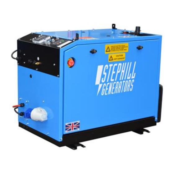
- Page 1 Issue 9 SSD6000W2 6kVA Super Silent Welfare Diesel Generator Handbook & Operation Manual +44 (0) 1933 677911 www.stephill-generators.co.uk...
-
Page 2: Table Of Contents
SSD6000W2 Contents 3 Introduction 11 Safety Considerations - cont. 11 Fire 3 Warranty Statement 11 Hot Parts 11 Long Term Storage 3 Amendments 4 Identification 12 Pre-start Checks 12 Check Oil Level - How to 4 Specification 12 Adding Engine Oil 5 AC Output &... - Page 3 SSD6000W2 17 Remote Module - Overview 18 Fault Finding 18 Before Fault Finding 18 Fault Finding - DSE 3110 21 Battery Charge System Fault Finding 22 Fuel System Bleeding Procedure 23 Service and Maintenance 23 Pre-service 23 Engine Service 23 Oil Change Locations...
-
Page 4: Introduction
No warranty claim will be considered by Stephill Generators Ltd unless any defective parts are available for inspection by us, or our nominees, to determine the reason or cause of failure, and Stephill Generators Ltd is given the option of repair or replacement. -
Page 5: Identification
SSD6000W2 Identification Each Stephill generator will have a Serial/Data plate fitted to the set. In most cases this can be found on the control/socket panel. Below is an example of the Serial/Data plate. Fig.1 Item No. Description Item No. Generator model type AC voltage output(s) Rated power, kVA &... -
Page 6: Ac Output & Protection
SSD6000W2 AC Output & Protection 230V AC Output Main alternator overload protected by double pole MCB. RCD protection for earth leakage. Note MCB = Miniature Circuit Breaker RCD = Residual Current Device All are suitably rated for the generator model type. -
Page 7: Control Panel Identification
SSD6000W2 Control Panel Identification The Stephill SSD60000W2 generators come with numerous different control panel version to suit different welfare applications. Below are the most common control panel types. Securi-Cabin (Panel No.2) Fig.2 Item No. Description Item No. Description DSE Control Module... -
Page 8: Manual & 2-Wire Remote (Panel No.7)
SSD6000W2 Item No. Description Item No. Description DSE Control Module Earth Stud - M8 Re-set Buttons Remote Control Socket Main 20A MCB Fuel Pump Prime Button Low Fuel Level Cable Manual & 2-Wire Remote (Panel No.7) Fig.4 Item No. Description Item No. -
Page 9: Information & Warning Signage
SSD6000W2 Information & Warning Signage The generator will have the following information and warning signage labels displayed. Fig.5 can be found on the main generator canopy door. Fig.5 Fig.6 can be found on the main generator canopy door. Fig.6 Fig.7 can be found on the main generator canopy roof. -
Page 10: Auxiliary Power
The standard reference condition for total barometric pressure is 1 bar. This corresponds to an altitude of approximately 100m. Above 100m the rated power must be reduced. Flammable Environment Stephill generators must not be used in a flammable environment. Saline Environment Operation of the machine in a saline environment will require additional corrosion protection. -
Page 11: Fuel
Earth Connection All Stephill products are fitted with an earth stud on the control panel this must be connected to an earthing system or spike. Any earth spike required is dependant on the local conditions of use. The size is determined by reference to current IEE regulations or to a competent electrician. -
Page 12: Noise
There is a risk of burns or serious mechanical injury. Long Term Storage For storage or long periods of inactivity, Stephill Generators recommend the following: Generators should be stored with oil filled to the correct capacity; Storage periods of 18 months and over may require special lubricants and treatments. -
Page 13: Pre-Start Checks
SSD6000W2 Pre-start Checks Before any attempt to start the generator please follow these important guidelines. STEPHILL GENERATORS LTD STRESS THAT THE ULTIMATE RESPONSIBILTY FOR THE SAFE USE OF THE GENERATOR RESTS WITH THE USER. Check Oil Level - How to It is recommended to check the oil level BEFORE EVERY START OPERATION or at least EVERY DAY - Ref. -
Page 14: Check Fuel Level
SSD6000W2 Check Fuel Level Stephill Generators do not supply the fuel tank with any of the SSD6000W2 range of generators. Most welfare cabin suppliers/manufacturers have a means to check the fuel level in their own fuel tanks. Ensure there is enough fuel in the fuel tank. Some models are equipped with a "Low Fuel Level" switch from a external fuel tank, this may prevent the generator from starting and/or shut the generator down when the fuel level becomes very low. -
Page 15: Manual & 2-Wire Remote (Panel No.7)
Manual & 2-Wire Remote (Panel No.7) This type of SSD6000W2 can be operated (started and stopped) by the DSE 3110 on the generator control panel manually and it also has the facility to be operated via a 2-wire start function remotely via a switch or a on-demand switch. -
Page 16: Dse 3110 - Remote Start/Stop
This is the primary method to operate the SSD6000W2 range of generators. The DSE 3110 module will remain in a sleep mode (display screen not illuminated) until a remote start request is made. -
Page 17: Dse 3110 Control Module - Overview
SSD6000W2 DSE 3110 Control Module - Overview Page Order Engine Speed Generator Volts (AC) Generator Frequency Engine Run Time Battery Volts (DC) Fig.12 Fig.13 Description of Controls Fig.12 show the layout and control buttons of the DSE 3110 control module. -
Page 18: Remote Module - Overview
SSD6000W2 Remote Module - Overview Some SSD6000W2 model variants use a Remote Module that is supplied by Stephill Generators Ltd. This remote module is an extension of the DSE 3110 control module on the generator. In most cases the generator cannot be operated unless this Remote Module is plugged into the generator. -
Page 19: Fault Finding
Reference wiring diagram(s) in this handbook - The diagrams will be correct as to the time of printing. Stephill reserve the right to change the wiring diagrams without prior warning. Fault Finding - DSE 3110 Most common faults can be Identified by the fault icon displayed on the right hand side of the LCD screen. - Page 20 SSD6000W2 Fault Icon Possible Cause Check ● Check the condition of the air filter - Replace Air Filter if necessary. ● If possible run the generator from a separate Contaminated Fuel fuel source from the fuel tank. If none of the above solve the issue then a closer inspection of the engine would be advised e.g.
- Page 21 SSD6000W2 Fault Icon Possible Cause Check The no-load frequency/rpm should measure approximately 52.5Hz/3150rpm Low AC Voltage Low Hz/Frequency could indicate the engine is running too fast. Warning - It is not recommended to adjust the engine speed unless absolutely High necessary.
-
Page 22: Battery Charge System Fault Finding
SSD6000W2 Fault Icon Possible Cause Check AC Output Fault MCB & RCD ● Check the MCB & RCD are switched on (up). Generator starts and runs but ● Check for any loose or broken wires in the AC Socket Outlet panel mounted socket. -
Page 23: Fuel System Bleeding Procedure
SSD6000W2 Remove No.26 & No.27 from the stator, start and run the set and measure the AC voltage between the two Green/White wires - this should measure 38V AC. If no AC voltage can be measured - replace the dynamo stator. -
Page 24: Service And Maintenance
SSD6000W2 Service and Maintenance Pre-service Warning - Do not attempt to carry out any service or maintenance work on the generator whilst the engine is running. Always isolate/disconnect the battery prior to working on the engine or alternator. Engine Service Keeping to the maintenance schedule recommended by the engine manufacture will ensure your generator engine will perform at its optimum efficiency. -
Page 25: Generator Access
Fig.16 Generator Access The SSD6000W2 generator has been designed to fit into a compact space within a welfare unit. To assist with service and/or maintenance the creative design also allows for full access of the generator. Below is the step- by-step process to assist with this operation. - Page 26 SSD6000W2 2. Silencer - Undo the two M8 silencer retaining bolts as shown in Fig.20. Be aware of the gasket - Fig.21, between the silencer and the manifold pipe. This is reusable and should be kept safe until reassembly. Fig.20...
- Page 27 SSD6000W2 5. Air Intake Hose - Fig.25 Undo the jubilee clip that holds the air intake hose on the air filter housing. Remove the hose from the air filter housing. Fig.25 6. Generator Release - The generator on the frame can now be pulled out of the canopy as shown in Fig.26.
-
Page 28: Alternator Service
STEPHILL GENERATORS LTD STRESS THAT THE ULTIMATE RESPONSIBILTY FOR THE SAFE USE OF THE GENERATOR RESTS WITH THE USER. Spares Engine Consumable Service Spares Basic Yanmar engine service kits are available form Stephill Generators, below are the individual parts complete with part numbers. Description Part No. -
Page 29: Control Panel - Dc Components - Standard Dse 3110
Silencer Kit Complete 026-2008 Silencer Mk3 022-2106 Manifold Pipe Mk3 026-2108 Tail Pipe Mk3 026-2121 L100 Engine Exhaust Gasket 029-0049 Silencer System Gasket - SSD6000W2 026-2020 Fiberglass Sleeve - (500mm) 023-1098 35mm U-Clamp 027-0058 Silencer System Mounts 027-0072 Remote Control Module 026-2008 Remote Module - ACM725PH - (hours run meter &... - Page 31 SSD6000W2 DS Non-Service Side 026-2110 SSD6000W2 Mark 3 Roof 026-1184 026-1146 SSD6000W2 Lifting eye SSD6000W2 DS Silencer Bracket 026-2115 SSD6000W2 DS Tail Pipe Cross Member 026-2116 SSD6000W2 Skid 026-1111 SSD6000W2 Mark 3 Tail Pipe Bracket 026-1183 SSD6000W2 Air Inlet Baffle 026-1147...
- Page 35 Blank Page...
- Page 36 Stephill Generators Ltd. Wallis Close, Park Farm South, Wellingborough, Northants, NN8 6AG. Copyright 2022 © Stephill Generators Ltd...
Need help?
Do you have a question about the SSD6000W2 and is the answer not in the manual?
Questions and answers