Table of Contents
Advertisement
Quick Links
Advertisement
Table of Contents

Subscribe to Our Youtube Channel
Related Manuals for Pratissoli SK Series


Summary of Contents for Pratissoli SK Series
- Page 1 Menu SK Series Repair Manual...
-
Page 3: Table Of Contents
INDEX 1. INTRODUCTION 2. REPAIR INSTRUCTIONS 2.1 Repair of the mechanical part .....................4 2.1.1 Dismantling the mechanical part ................5 2.1.2 Assembling the mechanical part...............16 2.1.3 Classes of increase....................31 2.2 Repair of the hydraulic part ....................32 2.2.1 Dismantling the head – liners – valves .............32 2.2.2 Assembling the head –... -
Page 4: Introduction
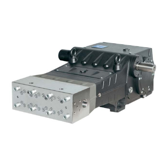
1. INTRODUCTION This manual contains the instructions for the repair of the SK family of pumps. It must be carefully read and understood before any operation is carried out on the pump. The proper functioning and lifetime of the pump depends on correct use and proper maintenance. Interpump Group declines all responsibility for damage caused due to negligence and/or failure to observe the instructions described in this manual. -
Page 5: Dismantling The Mechanical Part
2.1.1 Dismantling the mechanical part The correct sequence is as follows: Completely empty the pump of oil, as indicated in 2.1. Separate the head and the spacer for liners from the pump casing as shown in 2.2.1 (from fig.106 to fig.109). Remove the upper inspection cover and the lower inspection cover by unscrewing the 4+4 attachment screws, as shown in point 2.2.3 (fig.120 and fig.121). - Page 6 Take out the oil seal covers by screwing a threaded bar or an extractor M6 screw in the holes in the cover (pos. , fig.4) and take out the covers from the pump group (pos. , fig.5). fig. 4 fig. 5 Take out the radial seal ring (pos.
- Page 7 Unscrew the attachment screws of the shaft end cover (pos. , fig.9) and slip the cover off the PTO shaft. fig. 9 Unscrew the casing cover attachment screws (pos. , fig.10) and remove it. Slip off the O-ring and replace it if necessary.
- Page 8 Insert a shim under the shank of the central connecting rod, to stop the rotation of the crankshaft (pos. fig.13). fig. 13 Unscrew and take out the bush locking flange attachment screws, from both sides (pos. , fig.14). The bush locking flanges must be left in position (pos. , fig.15).
- Page 9 Remove the shim from under the shank of the central connecting rod. Unscrew the connecting rod screws (pos. , fig.18). fig. 18 Dismantle the small ends of the connecting rods with the half-bearings. During this operation take particular care to note the order in which the parts are removed. The connecting rod small ends and the big end halves must be reassembled in exactly the same order and pairings in which they were dismantled.
- Page 10 Take out both of the pressure bushes (pos , fig.21). fig. 21 Separate the bush locking flange from the pressure bush (pos , fig.22). fig. 22 Unscrew the screws of the two bearing support covers (pos. , fig.23). fig. 23...
- Page 11 Apply an M16 threaded pin to one end of the crankshaft (pos. , fig.24) and, while keeping it raised, take out the bearing support cover complete with bearing and O-ring (pos. , fig.25). To help with their removal, use 2 x M10 grub screws or screws (pos. , fig.24) as extractors.
- Page 12 Take out the radial seal ring (pos. , fig.29) and the outside O-ring (pos. , fig.30) and the lubrication hole O-ring (pos. , fig.31). fig. 29 fig. 30 fig. 31 Roll back the three connecting rods as far as possible (until they touch the crankshaft). Using a striking hammer or mallet (pos.
- Page 13 Slip the internal bearing rings off the PTO shaft (pos. , fig.34) and also slip off the two internal bearing spacers (pos. , fig.34). fig. 34 The internal and external bearing rings must be reassembled in exactly the same order and pairings in which they were dismantled.
- Page 14 Advance the big end halves in the direction of the hydraulic part and lock them in place using the special device (order code 27566200) (pos. , fig.39). fig. 39 Move the crankshaft from the lower part of the casing (pos. , fig.40).
- Page 15 Couple the big end halves to the small ends that were previously dismantled, with reference to their numbering scheme (pos. , fig.43). fig. 43 Remove the two pin-locking Seeger rings using the correct tool (pos. , fig.44). fig. 44 Slip out the pin (pos. , fig.45) and take out the connecting rod (pos.
-
Page 16: Assembling The Mechanical Part
To separate the stem from the piston head, it is necessary to unscrew the hexagonal-head M10 screw using a no. 17 socket wrench (pos. , fig.47). fig. 47 Complete the dissassembly of the mechanical part by removing the oil level lights, the eyebolts and the 90° quick-fit connection. - Page 17 Connect the stem to the piston head. Insert the Ø5 roll pin in the hole on the piston head (pos. , fig.49) and connect the stem to the piston head using a M10x35 screw (pos. , fig.50). fig. 50 fig. 49 Place the stem in a vice, closing the teeth of the vice on the two flat areas, and proceed with setting, using a torque wrench (pos.
- Page 18 Lock the three assemblies using the special device (order code 27566200) (pos. , fig.41). Insert the crankshaft through the rear opening of the casing and lay it on the bottom. The crankshaft must be inserted into the casing so that the teeth on the ring bevel gears are oriented as shown in fig.52.
- Page 19 From one side of the casing, insert the bearing lubrication bush (pos. , fig.54) and an external bearing ring (pos. , fig.55) using a pad and a mallet or striking hammer. fig. 55 fig. 54 Remove the device for locking the connecting rods (order code 27566200) (pos. , fig.41) and roll back the connecting rods until they touch the crankshaft.
- Page 20 From the side of the casing where the PTO shaft was inserted, proceed to insert the bearing lubrication bush (pos. , fig.58) and an external bearing ring (pos. , fig.59) using a pad and a mallet or striking hammer. fig. 59 fig.
- Page 21 Pre-assemble the left and right PTO bearing covers: Insert the radial seal ring into the PTO bearing cover using the device (order code 27539500) (pos. fig.64). Before proceeding with the assembly of the radial seal ring, verify the condition of the seal lip. If it is necessary to replace it, position the new ring as shown in fig.65.
- Page 22 Mount one of the PTO bearing covers (left or right) on the pump casing (pos. , fig.68) and attach it with 4 x M8x30 screws (pos. , fig.69). Be careful of the direction of assembly of the cover. The lubrication hole in the cover must correspond to the hole in the casing.
- Page 23 fig. 71 TRADUZIONE TERMINI conicità = conicity The bearing in fig.71 has a conical internal ring. Verify that the conicity is from the outside to the inside, to allow the subsequent insertion of the bush. Apply the O-ring to the outside of the bearing support cover (pos. , fig.72).
- Page 24 Fasten the bearing support covers with 6+6 x M10x30 screws (pos. , fig.75). Set the screws with a torque wrench, as shown in section 3. fig. 75 Partly insert the two pressure bushes, keeping the crankshaft lifted up by means of the previously-mounted M16 pin (pos.
- Page 25 The pressure bush must be inserted dry (no oils or lubricants). Insert the bush until the outside (conical) surface perfectly couples with the inside of the bearing. During insertion, make sure that the bearing stays in contact with the crankshaft shoulder. Repeat the operation on the other side.
- Page 26 Apply the lower half-bearings to the small ends (pos. , fig.83), making sure that the lugs on the half- bearings are positioned in the slots on the small ends (pos. , fig.83). Attach the small ends to the big end halves using the M12x1.25x87 screws (pos. , fig.84).
- Page 27 Measure the distance X indicated in fig.86 between the conical bush and the crankshaft bearing. fig. 86 Screw in the M16 screw until there is a reduction in the distance X of between 0.7 mm and 0.8 mm (fig.87). fig. 87 Repeat the operation on the other side.
- Page 28 Remove the anti-rotation shim from under the shank of the central connecting rod. Mount the two bearing covers (with their O-rings) (pos. , fig.90) using 6+6 x M8x20 screws (pos. , fig.91). Set the screws with a torque wrench, as shown in section 3. fig.
- Page 29 Position the O-ring (pos. , fig.95) on the seat of the oil seal cover, and insert the assembly into the casing in the seat provided (pos. , fig.96). fig. 96 fig. 95 Make sure that the cover completely enters its seat (pos. , fig.97), being careful not to damage the lip of the radial seal ring.
- Page 30 Screw in the three pistons (pos. , fig.101) and set using an open-ended torque wrench as shown in section3. fig. 101 Insert the O-rings on the two inspection covers (pos. , fig.102) and mount the covers using 4+4 x M6x14 screws (pos.
-
Page 31: Classes Of Increase
Apply the lug to the PTO shaft (pos. , fig.105). fig. 105 2.1.3 Classes of increase INCREASE TABLE FOR CRANKSHAFT AND CONNECTION ROD HALF-BEARINGS Recovery classes Upper Half- Lower Half- Grinding on shaft pin diameter (mm) bearing Code bearing Code (mm) 0.25 90931100... -
Page 32: Repair Of The Hydraulic Part
2.2 Repair of the hydraulic part 2.2.1 Dismantling the head – liners – valves The head does not need periodic maintenance. Operations are limited to inspection or replacement of the valves, when necessary. To extract the valve assemblies work as follows: Loosen, without removing, the M10x140 screws affixing the liners to the head (pos. - Page 33 Remove the O-rings of the gasket supports (pos. , fig.110) and slip off the spacer for liners from the liner assemblies (pos. , fig.111). fig. 110 fig. 111 Remove the M10x140 screws affixing the liners to the head (pos. , fig.112) and take out the liner assemblies (pos.
- Page 34 If the valve seats are stuck on the head due to the formation of limescale or oxide, they must be freed by inserting the special tool (order code 034300020 for SK20-22-24, or 034300010 for SK26-28-30) into the outlet hole (pos. , fig.115).
-
Page 35: Assembling The Head - Liners - Valves
Take out the outlet cotters (pos. , fig.117) and their holders (pos. , fig.119) and the springs (pos. fig.118) check their state of wear and, if necessary, replace them. (Replace them in any case at the intervals specified in section 11 of the Manual for Use and Maintenance.) fig. -
Page 36: Dismantling The Piston - Supports - Seals Assembly
2.2.3 Dismantling the piston – supports – seals assembly The piston assembly does not need periodic maintenance. Operations are limited to a visual check of the draining of the cooling circuit. If there are anomalies/oscillations in the outlet pressure gauge, or pulsations in the cooling circuit drainage pipe (if elastic), then the seal packing must be checked and, if necessary, replaced. - Page 37 Remove the M8x50 screws affixing the support to the liner (pos. , fig.124) and separate the support from the liner (pos. , fig.125). fig. 124 fig. 125 Remove the Seeger ring and the seal retainer ring (pos. , fig.126) and with a special plastic pin, take out the LP (low pressure) gasket seal (pos.
-
Page 38: Assembling The Piston - Supports - Seals Assembly
With the liner separated from the seal support and with a special plastic pin (pos. , fig.128) push out the HP (high pressure) packing (pos. , fig.129). At every dismantling the HP packing (pos. , fig.129) must be replaced. fig. 128 fig. - Page 39 Insert the H.P. (high pressure) packing (pos. , fig.132). Given the slight interference between the seal and the liner, to avoid causing damage we recommend using the special tool (order code 27540100 for SK20, SK22 and SK24, code 27540900 for SK26, for SK28 and for SK30) (pos. , fig.133). fig.
- Page 40 Insert the anti-extrusion ring and the gasket bush (pos. , fig.136 - 137 and 138). The gasket bush must be inserted into the liner with the two discharges facing outside (casing side) as shown in fig. 137. fig. 136 fig. 137 fig.
- Page 41 The L.P. seal must be inserted into the liner with the seal lip in the direction of travel of the piston (pos. , fig.139 and 140), lightly lubricating the outside diameter with silicone grease (OKS 1110 type). Replace the L.P. seal when it is worn. fig.
-
Page 42: Screw Calibration
Assemble the support/liner assembly, manually tightening the M8x50 screws as shown in fig.143, and then proceeding with setting with torque wrench as shown in section 3. fig. 143 3. SCREW CALIBRATION Screws are to be fastened exclusively using a torque wrench. Exploded Fastening Description... - Page 43 fig. 144 TRADUZIONE Tightening of screws for gasket supports, position 26 Tighten M8x50 screws in the sequence indicated (1-2-3-4-5-6-7-8-9-10), performed in a single phase and with the specified torque...
- Page 44 fig. 145 TRADUZIONE Tightening of screws for head and screws for liners, positions 14 and 13 OPERATION 1: Tightening M16x280 screws (position 14) in two phases phase = 250 Nm phase = 333 Nm OPERATION 2: Tightening M10x140 screws (position 13) in four phases phase = 40 Nm phase = 65 Nm phase = 83 Nm...
-
Page 45: Repair Tools
4. REPAIR TOOLS Pump maintenance can be carried out using simple equipment for dismantling and reassembling the components. The following equipment is available: For assembly: Piston head radial seal ring code 27910900 PTO shaft radial seal ring code 27539500 Gasket bush code 27911200 (SK20), code 27911400 (SK22), code 27911500 (SK24) code 27911600 (SK26), code 27911700 (SK28), code 27911800 (SK30) HP seal packing... - Page 46 Offenders will be prosecuted according to the laws in force. PRATISSOLI a brand of INTERPUMP GROUP S.P.A. 42049 S.ILARIO - REGGIO EMILIA ( ITALY ) Tel. +39 - 0522 - 904311 Fax +39 - 0522 - 904444 E-mail: info@pratissolipompe.com...
Need help?
Do you have a question about the SK Series and is the answer not in the manual?
Questions and answers