Table of Contents
Advertisement
Available languages
Available languages
Quick Links
Einbau- und Bedienungsanleitung
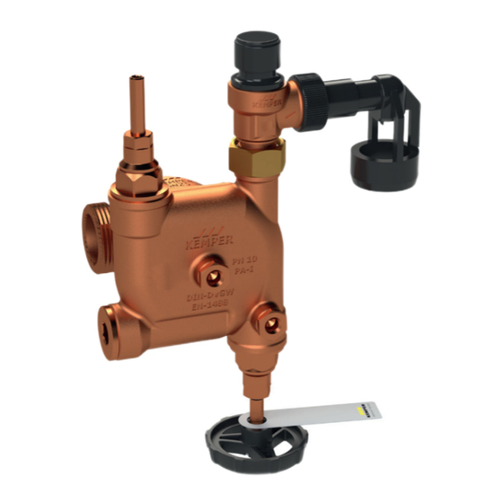
Sicherheitsgruppe, DN 20 mit Anschlussmöglichkeiten DN 15 - DN 32
Fig. 714 - 716
Installation and Operating Manual
Safety group, DN 20 with connection possibilities DN 15 - DN 32
Fig. 714 - 716
Varianten: Funktionsmodul inkl. Basis-Modul
Fig. 714 0G
mit Sicherheitsventil 0,6 MPa (6 bar)
Fig. 715 0G
mit Sicherheitsventil 0,8 MPa (8 bar)
Fig. 716 0G
mit Sicherheitsventil 1,0 MPa (10 bar)
Variants: Function module incl. basic module
Fig. 714 0G
with safety valve 0,6 MPa (6 bar)
Fig. 715 0G
with safety valve 0,8 MPa (8 bar)
Fig. 716 0G
with safety valve 1,0 MPa (10 bar)
2
11
Advertisement
Table of Contents

Related Manuals for Kemper 7140G02000


Summary of Contents for Kemper 7140G02000
- Page 1 Einbau- und Bedienungsanleitung Sicherheitsgruppe, DN 20 mit Anschlussmöglichkeiten DN 15 - DN 32 Fig. 714 - 716 Installation and Operating Manual Safety group, DN 20 with connection possibilities DN 15 - DN 32 Fig. 714 - 716 Varianten: Funktionsmodul inkl. Basis-Modul Fig.
- Page 2 0,6 MPa (6 bar) Fig. 715 0G with safety valve 0,8 MPa (8 bar) Fig. 716 0G with safety valve 1,0 MPa (10 bar) DIN EN 1488 | DIN 4753-1 | DIN 1988-200 2 /16 –K4100714000001-00 / 09.2021– © www.kemper-olpe.de...
-
Page 3: Technische Daten
L4 [mm] 57,5 57,5 57,5 L5 [mm] L1 [mm] T1 [mm] 51,5 51,5 51,5 T2 [mm] T3 [mm] 20,6 27,5 27,5 max. Durchfluss- wert (K ) [m³/h] Gewicht [kg] 2,10 2,84 2,88 © www.kemper-olpe.de – 09.2021 / K4100714000001-00 – 3 /16... - Page 4 TRD 721, da der engste geforderte Strömungs- die Einbaubedingungen für durchmesser von 14 mm im Ventilkegel des Mem- Speicherwasserwärmer mit einem bransicherheitsventils vorhanden ist (siehe Tafel 4, Nenninhalt ≤200 bis ≤1000 Liter nach TRD 721). 4 /16 –K4100714000001-00 / 09.2021– © www.kemper-olpe.de...
- Page 5 DN 20, DN 25 oder DN 32 zu wählen. Die Sicherheitsgruppe DN 20 kann somit für eine Rohrdimension von DN 20 bis DN 32 (Trinkwasser (kalt)- Zuleitung) eingesetzt werden. © www.kemper-olpe.de – 09.2021 / K4100714000001-00 – 5 /16...
-
Page 6: Montage
Gründen mehr Bögen oder eine größere Länge erforderlich, so muss die gesamte Abblaseleitung eine Nennweite größer ausgeführt sein. Mehr als 3 Bögen sowie eine Länge über 4 m sind unzulässig. Dabei muss die Abblaseleitung mit Gefälle verlegt werden. 6 /16 –K4100714000001-00 / 09.2021– © www.kemper-olpe.de... - Page 7 Bereich 3 absperrt. Im weiteren Verlauf steht hierbei das Wasser mit vollem Druck gegen das Sicherheitsventil an und wird durch die mittlere Öffnung 5 wieder in das KEMPER Basis-Modul geleitet. Hier kann optional mittels Manometer der aus- gangsseitige Druck angezeigt werden.
-
Page 8: Wartung
RV-Einsatz demontieren und durch auszutauschen. einen neuen RV-Einsatz (siehe Ersatzteilliste) ersetzen. Nach der Wartung sind die Absperreinrich- tungen wieder zu öffnen. Bei Ersatz des RV ist eine erneute Wartung erforderlich. Ersatzteile und Zubehör 8 /16 –K4100714000001-00 / 09.2021– © www.kemper-olpe.de... -
Page 9: Ersatzteile Und Zubehör
K91007140000200 Absperroberteil E010917302020KP Wartungsoberteil E01017140002000 Manometer T51007000000100 Zubehör Überströmkappe B31007000000100 Zubehör Verschlussstopfen 1/4 J81011730000600 Wartungsstopfen J81097140000100 RV-Patrone DN 20 P41001580002000 Drucksensor 1380000600 Zubehör Funktionsbauteile Hauptabsperrung Wartungsabsperrung Sicherheitsventil RV Wartungsbohrung Manometeranschluss RV-Prüfanschluss © www.kemper-olpe.de – 09.2021 / K4100714000001-00 – 9 /16... - Page 10 10 /16 –K4100714000001-00 / 09.2021– © www.kemper-olpe.de...
- Page 11 Einbau- und Bedienungsanleitung Sicherheitsgruppe, DN 20 mit Anschlussmöglichkeiten DN 15 - DN 32 Fig. 714 - 716 Installation and Operating Manual Safety group, DN 20 with connection possibilities DN 15 - DN 32 Fig. 714 - 716 Varianten: Funktionsmodul inkl. Basis-Modul Fig.
-
Page 12: Safety Instructions
Variants: Function module incl. basic module Fig. 714 0G with safety valve 0,6 MPa (6 bar) Fig. 715 0G with safety valve 0,8 MPa (8 bar) Fig. 716 0G with safety valve 1,0 MPa (10 bar) 12 /72 – K410061500001-00 / 09.2021– © www.kemper-olpe.de... -
Page 13: Technical Data
L4 [mm] 57,5 57,5 57,5 L5 [mm] L1 [mm] T1 [mm] 51,5 51,5 51,5 T2 [mm] T3 [mm] 20,6 27,5 27,5 max. flow rate (kvs) [m³/h] weight [kg] 2,10 2,84 2,88 © www.kemper-olpe.de – 09.2021 / K4100714000001-00 – 13 /20... - Page 14 14 mm in the cone of the diaphr- water heaters with a nominal capacity am-type safety valve (see Table 4, TRD 721). ≤ 200 to ≤ 1000 litres, in accordance 14 /20 –K4100714000001-00 / 09.2021– © www.kemper-olpe.de...
-
Page 15: Pressure Drop
DN 20, DN 25 or DN 32, according to the selected pipe dimensions. The safety group in size DN 20 can, therefore, be used for pipe dimensi- ons from DN 20 to DN 32 ((cold) drinking water piping). © www.kemper-olpe.de – 09.2021 / K4100714000001-00 – 15 /20... -
Page 16: Installation
Installation The safety group is installed together with the above the highest possible water level of the drinking KEMPER basic module and the fittings in the piping water heater, thereby conducting the cold water to the drinking water making it possible to avoid the drainage of hot water heater (heed direction of flow!). -
Page 17: Initial System Checkout
(E) must be opened for a short time in order to eliminate any air pockets. Flow through the safety group With the KEMPER safety group the water is con- ducted through the KEMPER basic module into the outer annular gap (chamber 1 of the safety group housing). -
Page 18: Maintenance
(see spare parts list). Upon com- pletion of the maintenance work, close the isolating valves again. When inspecting the backflow preventer, the maintenance procedure must be repeated. Accessories | Spare parts list 18 /20 –K4100714000001-00 / 09.2021– © www.kemper-olpe.de... - Page 19 J81097140000100 Backflow preventer cartridge P41001580002000 DN 20 Pressure sensor 1380000600 Accessories Functional components Main isolating valve Maintenance valve Safety valve Backflow preventer maintenance hole Pressure gauge connection Backflow preventer test connection © www.kemper-olpe.de – 09.2021 / K4100714000001-00 – 19 /20...
- Page 20 Gebr. Kemper GmbH + Co. KG Service-Hotline +49 2761 891-800 Harkortstraße 5 www.kemper-olpe.de D-57462 Olpe info@kemper-olpe.de 20 /20 –K4100714000001-00 / 09.2021– © www.kemper-olpe.de...
Need help?
Do you have a question about the 7140G02000 and is the answer not in the manual?
Questions and answers