Table of Contents
Advertisement
Quick Links
Installation and operating instructions
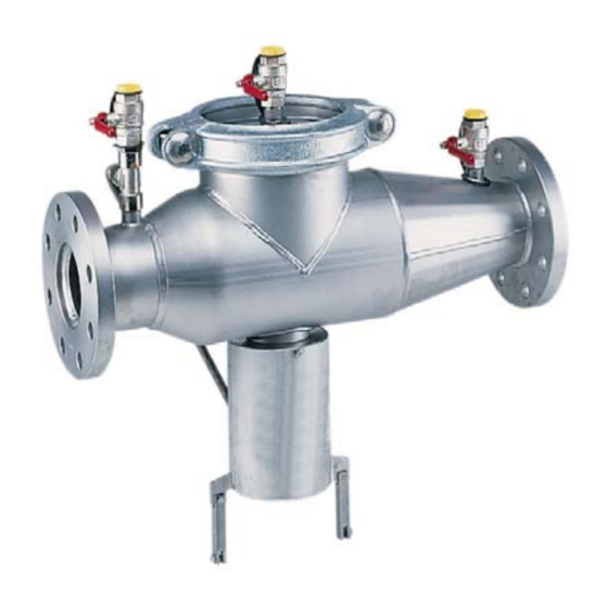
KEMPER Backflow Preventer BA Figure 361
1. Prerequisites for installation
Install the backflow preventer in
frost-free areas only!
Comply with standards:
Provide a drain line!
Application area
According to DIN EN 1717, in order to maintain flawless functioning of the BA backflow preventer, a flanged dirt trap
must be installed in the direction of flow before the BA backflow preventer. Type BA backflow preventers that accord
with DIN EN 12729 are used to secure drinking water plants against back pressures and siphon back flow. Fluids up to
and including Fluid Category 4 as per DIN EN 1717/1988-100 are secured. They can be used for residential buildings,
industrial and commercial purposes with consideration of their specifications. Normally (normal functioning with pressure
fluctuations), the vent hole of the middle pressure chamber only allows a few drops through. During malfunctions,
the vent hole can allow the full volume flow of the service pipe through. For that reason, dimension the wastewater
connection to be sufficiently large according to DIN EN 12056 and DIN 1986-100. Assume the volume flow that could arise
through the service pipe on the backflow preventer BA (pay attention to the nominal flow rate!). The backflow preventer
BA can secure the following hazard potential in accordance with the Fluid Category:
Category 4 (applies to backflow preventer BA)
Fluids that present a health hazard to humans due to the presence of one or more toxic or highly toxic substances or
one or more radioactive, mutagenic or carcinogenic substances.
The higher the classification, the greater the risk potential. For each category, DIN EN 1717 stipulates specific protection
valves. The Backflow Preventer BA, Figure 361 is approved without restriction for use up to and including Category 4. A
continual bacterial risk (Fluid Category 5) in extant piping systems must not exist.
2. Operating principle
The KEMPER BA Backflow Preventer is subdivided into 3 zones. In Zone 1, the pressure is higher than in Zone 2 and there
again higher than in Zone 3. A drain valve is connected to Zone 2, which opens latest when the pressure difference between
Zones 1 and 2 has decreased to less than 0.14 bar. The water from Zone 2 flows outdoors. That precludes the risk of back-
pressure or siphon back flow in the supply network. The pipeline is interrupted and the drinking water network is protected.
Intermittent dripping from the BA Backflow Preventer at the drain valve is not necessarily a malfunction.
Under such circumstances, the BA Backflow Preventer separates as intended!
DIN EN 1717, DIN 1988
DIN EN 12056, DIN 1986-100
Comply with the direction of flow!
- 1 -
Advertisement
Table of Contents

Related Manuals for Kemper 361


Summary of Contents for Kemper 361
- Page 1 2. Operating principle The KEMPER BA Backflow Preventer is subdivided into 3 zones. In Zone 1, the pressure is higher than in Zone 2 and there again higher than in Zone 3. A drain valve is connected to Zone 2, which opens latest when the pressure difference between Zones 1 and 2 has decreased to less than 0.14 bar.
-
Page 2: Installation
31.3 32.6 52.6 Table 1: Dimensions: Backflow Preventer BA Figure 361 3. Installation The BA Backflow Preventer must be installed level. Provide cut-off valves in front of and behind the backflow preventer. In addition, a dirt trap must be connected upstream which prevents the backflow preventer from damage and functional impairments due to coarse dirt. - Page 3 Figure 2: Connection area Figure 3: BA Backflow Preventer protection device with installation prerequisites and dimensions. Connection sizes (Dimensions in mm) Table 2: Dimensions for installation prerequisites - 3 -...
- Page 4 3.1 Notes for secure installation If there are supply pressure fluctuations, without water removal a short triggering of the drain valve can occur. For that reason, we recommend installing a pressure reducing valve before the backflow preventer. The room in which the backflow preventer is installed must be freely accessible at all times and always be frost free. Ensure good ventilation.
- Page 5 The manufacturer recommends replacing the cartridge every 10 years. Comply with local regulations. Measuring instrument for differential pressure measurement: Suitable differential pressure manometer; The KEMPER differential pressure measurement case, Figure 360 99, is recommended. 5.1 Connect test adapter...
- Page 6 5.2 Preparing the differential pressure manometer - Connect the test hose with the adapter *+* and *-* of the differential pressure manometer to each side. 5.3 Connect differential pressure manometer + ‐ for function test inlet anti-pollution check-valve and drain valve - For each test hose, plug on and latch a quick coupler to the adapter (bleeder valves must be closed on the hoses.) - Connect the test hose of Test valve A to...
- Page 7 - Close the stop valve before and after the valve. - Using the bleeder valve on the test hose (Test valve B), + ‐ slowly bleed the pressure of the middle pressure zone and watch the differential pressure display at the same time. The differential pressure rises until the anti-pollution check-valve starts to open.
- Page 8 5.6 Connect differential pressure manometer + ‐ and absolute pressure manometer for function test output anti-pollution check-valve - Connect the test hose from Test valve B to the connection marked ``-`` on the differential pressure manometer. - Connect absolute pressure manometer with adapter to Test valve C.
- Page 9 6. Removal, installation and cleaning the drain valve Both anti-pollution check-valves and the drain valve can be removed for maintenance purposes. All work can be performed without removing the housing from the pipeline (inline service). Only authorised specialists are allowed to perform maintenance. Close cut-off valves 1 and 2.
-
Page 10: Troubleshooting
Have all malfunctions that could impair safety repaired immediately. The BA Backflow Preventer, Figure 361, is intended solely for the application areas named in these installation and operating instructions. Any different use or use beyond and above that is considered non-intended usage. -
Page 11: Flow Diagram
12. Accessories KEMPER differential pressure measuring case Differential pressure manometer in a representative aluminium case, ideal for inspecting and maintaining all KEMPER BA Backflow Preventers, Figures 360 and 361 Content of the Differential Pressure Measurement Kit, Figure 360 99... -
Page 12: Spare Parts
13. Spare parts Anti-pollution check valve, supply side Anti-pollution check valve, discharge side DN 65 – DN 100 Figure 361 98 002, DN 65 - DN 100 Figure 361 98 003, DN 150 Figure 361 98 006 010 DN 150 Figure 361 98 007... - Page 13 - 13 -...
Need help?
Do you have a question about the 361 and is the answer not in the manual?
Questions and answers