Advertisement
Available languages
Available languages
Quick Links
Einbau- und Bedienungsanleitung
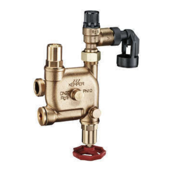
KEMPER Sicherheitsgruppe Modul S, DN 20
mit Anschlussmöglichkeiten DN 15 - DN 32
Fig. 714 – 716
Varianten: Funktionsmodul inkl. Basismodul
Fig. 714 0G
mit Sicherheitsventil 0,6 MPa (6 bar)
Fig. 715 0G
mit Sicherheitsventil 0,8 MPa (8 bar)
Fig. 716 0G
mit Sicherheitsventil 1,0 MPa (10 bar)
Varianten: Funktionsmodul ohne Basismodul
Fig. 714 00 001
mit Sicherheitsventil 0,6 MPa (6 bar)
Fig. 715 00 001
mit Sicherheitsventil 0,8 MPa (8 bar)
Fig. 716 00 001
mit Sicherheitsventil 1,0 MPa (10 bar)
Advertisement

Related Manuals for Kemper 714 0G


Summary of Contents for Kemper 714 0G
- Page 1 Einbau- und Bedienungsanleitung KEMPER Sicherheitsgruppe Modul S, DN 20 mit Anschlussmöglichkeiten DN 15 - DN 32 Fig. 714 – 716 Varianten: Funktionsmodul inkl. Basismodul Fig. 714 0G mit Sicherheitsventil 0,6 MPa (6 bar) Fig. 715 0G mit Sicherheitsventil 0,8 MPa (8 bar) Fig.
- Page 2 - eigenständige Modifikation am Produkt. - sonstige fehlerhafte Bedienung. DIN EN 1488 DIN 4753-1 Verwendung DIN 1988-2 Die KEMPER Sicherheitsgruppe Modul S, DN 20 nach DIN EN 1488, dient zur Absicherung der Drucküberschreitung an geschlossenen Trink- wassererwärmern (TWE). Mit der Sicherheitsgruppe können geschlossene Entsorgung Trinkwassererwärmer bis 150 kW Heizleistung >...
- Page 3 Bezeichnung Bestellnr. Basis-Modul 7000G02000 Sicherheitsventil inkl. E01097140102000 0,6 MPa Teleskop-Ablauftrichter E01097150102000 0,8 MPa E01097160102000 1,0 MPa Zylinderschraube M6 x 12 D31207140000100 O-Ring K91007140000100 O-Ring K91007140000200 Absperroberteil E010917302020KP Wartungsoberteil E01017140002000 Manometer T51007000000100 Zubehör Überströmkappe B31007000000100 Zubehör Verschlussstopfen 1/4 J81011730000600 Wartungsstopfen J81097140000100 RV-Patrone DN 20 P41001580002000 Drucksensor...
- Page 4 Bestellnr. 7140G02000 7140G02500 7140G03200 G 1 1/4 G 1 1/2 D1 [mm] D2 [mm] H1 [mm] H2 [mm] H3 [mm] 151,5 151,5 H4 [mm] 151,5 165,5 L2 [mm] 52,5 L3 [mm] 57,5 57,5 L4 [mm] 57,5 L5 [mm] L1 [mm] 51,5 51,5 T1 [mm]...
- Page 5 TW-Hausanschluss nach DIN 1988-2 Figur 714 – 716 Figur 145 Figur 712 Figur 710 Figur 713 KEMPER Sicherheitsgruppe geforderte Strömungsdurchmesser erfüllt die Einbaubedingungen für von 14 mm im Ventilkegel des Speicherwasserwärmer mit einem Membransicherheitsventils vorhan- Nenninhalt ≤ 200 bis ≤ 1000 Liter den ist (siehe Tafel 4, TRD 721).
-
Page 6: Montage
Zuleitungen gruppe waagerecht oder senkrecht in die durchzuspülen. Bei vorzeitigem Einbau (z. Kaltwasserzuleitung eingebaut werden. B. in der Rohbauphase) des KEMPER Basis- Sicherheitsgruppe immer mit der Damit kann im Wartungsfall das Ablassen senkrechten Hauptachse (Mem- von Warmwasser vermieden werden. - Page 7 Zusammenbau Siehe Lieferumfang Seiten 2/3 Zubehör | Ersatzteilliste Basis-Modul mittels Zylinder- Ablauftrichter muss starr schrauben M 6 x 12 (5) befestigen. Das Abblaseleitung verbunden werden. Nach MSV (3) nach der Druckprobe (siehe Punkt DIN 4753 Teil 1, darf die Abblaseleitung 4.
- Page 8 Durchströmung der Armatur Beim KEMPER Basis-Modul wird das Wasser durch den äußeren Ringspalt in die Kammer 1 des Sicherheitsgruppengehäuses geleitet. Von hier aus gelangt das Wasser in die Kammer Hauptabsperrein- richtung. Danach schließt sich Rückfluss- verhinderer an, der in Kammer 3 das Rückfließen des Wassers verhindert.
- Page 9 Installation and Operating Manual KEMPER module S safety group, DN 20 with connection possibilities DN 15 - DN 32 Fig. 714 – 716 Variants: Function module incl. basic module Fig. 714 0G with safety valve 0,6 MPa (6 bar) Fig. 715 0G with safety valve 0,8 MPa (8 bar) Fig.
- Page 10 - Incorrect installation and/or operating. - Unauthorised modification of the product. - Any other errors in operating. Standards | Directives The KEMPER Module S safety group, DN 20, to DIN EN 1488 DIN EN 1488, is used to safeguard self-contained DIN 4753-1 drinking water heaters against excess pressure.
- Page 11 Designation Art.-No. Basic module 7000G02000 Safety valve incl. E01097140102000 0,6 MPa telescopic drainage funnel E01097150102000 0,8 MPa E01097160102000 1,0 MPa Hex. socket head cap screw M6 x 12 D31207140000100 O-ring K91007140000100 O-ring K91007140000200 Top section E010917302020KP Maintenance top section E01017140002000 Pressure gauge T51007000000100 Accessories...
- Page 12 Art.-No. 7140G02000 7140G02500 7140G03200 G 1 1/4 G 1 1/2 D1 [mm] D2 [mm] H1 [mm] H2 [mm] H3 [mm] 151,5 151,5 H4 [mm] 151,5 165,5 L2 [mm] 52,5 L3 [mm] 57,5 57,5 L4 [mm] 57,5 L5 [mm] L1 [mm] 51,5 51,5 T1 [mm]...
- Page 13 Drinking water service connection to DIN 1988-2 Figure 714 – 716 Figure 145 Figure 712 Figure 710 Figure 713 Valve sizes narrowest flow Nominal volume of Valve size*) min. highest heater rating diameter min. the water space in l nominal size [DN] in [kW] [mm] ≤...
-
Page 14: Installation
DN 20, DN 25 or Pressure drop The flow rate achievable with the KEMPER drop in pressure has to be taken into safety group ((kvs value) of 4.52 m³/h) consideration when calculating the piping with a 100 MPa pressure drop is higher network. -
Page 15: Initial System Checkout
Assembly see Scope of delivery pages 2/3 Accessories | Spare parts list Mount basic module (2) in place by means must be rigidly connected to the blow-down of hexagon socket head cap screws M 6 x piping. According to DIN 4753 Part 1, the 12 (5). - Page 16 Flow through the safety group With the KEMPER basic module the water is conducted through the outer annular gap into chamber 1 of the safety group housing. From there the water passes to chamber 2, where the main isolating valve is situated.
Need help?
Do you have a question about the 714 0G and is the answer not in the manual?
Questions and answers