Table of Contents
Advertisement
Quick Links
EM3E Series EtherCAT Stepper Drive User Manual
User Manual
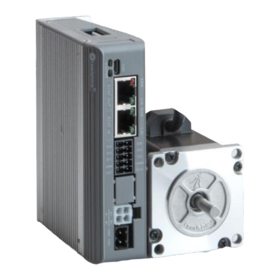
EM3E Series
EtherCAT Stepper Drive
For models of EM3E-522E, EM3E-556E and EM3E-870E
©2020 Leadshine Technology Co., Ltd.
Address: Floor 11, Block A3, Nanshan iPark, Xueyuan Avenue 1001, Shenzhen, Guangdong, 518055, China
Tel: (86)755-26409254
Fax: (86)755-26402718
Web:
www.leadshine.com
Sales:
sales@leadshine.com
Support:
tech@leadshine.com
Advertisement
Table of Contents

Related Manuals for Leadshine EM3E Series


Summary of Contents for Leadshine EM3E Series
- Page 1 EM3E Series EtherCAT Stepper Drive User Manual User Manual EM3E Series EtherCAT Stepper Drive For models of EM3E-522E, EM3E-556E and EM3E-870E ©2020 Leadshine Technology Co., Ltd. Address: Floor 11, Block A3, Nanshan iPark, Xueyuan Avenue 1001, Shenzhen, Guangdong, 518055, China...
- Page 2 EM3E Series EtherCAT Stepper Drive User Manual EM3E Passed the ETC Laboratory Conformance Tested EtherCAT ® is a registered trademark and patented technology, licensed by Beckhoff Automation GmbH, Germany. Thanks for purchasing Leadshine EM3E Series Products ◆ Please read this manual carefully before using product ◆...
- Page 3 EM3E Series EtherCAT Stepper Drive User Manual Record of Revisions Reversion Data Description of Release Signed V1.0 11/02/2017 Initial Release V1.2 06/01/2020 Add debug port, change ESI file...
- Page 4 Preface Preface Thank you for choosing EM3E EtherCAT stepper drive system of Leadshine Technology Co., Ltd. This manual gives required knowledge & precautions for using EM3E Series Stepper Drives. About EtherCAT: EtherCAT (Ethernet for Control Automation Technology) is open network communication using real-time Ethernet between masters and slaves developed by Beckhoff Automation GmbH, Germany.
-
Page 5: Table Of Contents
Contents Contents 1 Introduction................................7 1.1 Product Introduction..........................7 1.2 Features................................7 1.3 Check of Product............................7 1.3.1 Arrival inspection...........................7 1.3.2 Nameplate information....................... 8 1.3.3 Part number.............................8 1.3.4 Parts description..........................8 1.3.5 Accessory Cables........................... 9 2 Installation................................10 2.1 Storage and Installation Conditions....................10 2.1.1 Storage condition......................... - Page 6 Contents 4.2 Manufacture Specific Object......................23 4.3 I/O Configuration Object........................26 4.3.1 Input Ports Function Value...................... 26 4.3.2 Input Ports Filter Time & Polarity Value................28 4.3.3 Output Ports Function & Polarity Value................29 4.3.4 Main Control Output Function....................29 4.4 Motion Objects............................29 4.5 XML File or ESI File..........................
-
Page 7: Introduction
Cyclic Synchronous Position (CSP). The products can be matched with many brands of EtherCAT controller/PLC such as Beckhoff, Omron, Trio, Keneyce, etc. The EM3E series is highly reliable and affordable and performs excellently in many industrial applications such as solar equipment, textile, civil, robotics, power generation equipment, 3C, packaging... -
Page 8: Nameplate Information
EM3E Series EtherCAT Stepper Drive User Manual 1.3.2 Nameplate information 1.3.3 Part number 1.3.4 Parts description... -
Page 9: Accessory Cables
EM3E Series EtherCAT Stepper Drive User Manual 1.3.5 Accessory Cables Name Necessary Picture Description Model CABLE-M Tuning Cable Micro-USB cable USB1M5 Optional length: 0.1m, Yes, can use 0.2m, 0.3m, 0.4m, 1m, 1.5m, CABLE-TX Network cable party cable 2m, 3m,5m,7m, 10m,15m,... -
Page 10: Installation
EM3E Series EtherCAT Stepper Drive User Manual 2 Installation 2.1 Storage and Installation Conditions 2.1.1 Storage condition Correctly packaged and store in a clean and dry environment where direct sunlight is avoided. Store within an ambient temperature ranging from -20 to +65 ... - Page 11 EM3E Series EtherCAT Stepper Drive User Manual The drive should be mounted perpendicular to the wall or in the control panel. In order to ensure the drive is well ventilated, ensure that the all ventilation holes are not ...
-
Page 12: Production Specifications
EM3E Series EtherCAT Stepper Drive User Manual 3 Production Specifications 3.1 Electrical and Operating Specifications 3.1.1 EtherCAT Specifications Name Description Physical Layer Ethernet-100BASE-TX RJ45: EtherCAT Input and EtherCAT Output Communication Connector Micro-USB: Tuning port Topology Line, Tree Baud Rate 100Mbps (full-duplex-channel) -
Page 13: Cable Specifications
EM3E Series EtherCAT Stepper Drive User Manual Environment Avoid dust, oil ,fog and corrosive gases Operating 0-40℃ (32 F – 104 F) Temperature Storage -20℃-65℃ (-4 F – 149 F) Temperature Operating Environment Humidity 40-90%RH Vibration 10-55Hz/0.15mm Mount Vertical or horizontal mounting 3.2 Cable Specifications... -
Page 14: Ethercat Communication Cable
EM3E Series EtherCAT Stepper Drive User Manual interference Please connect surge absorber to inductive device, such as anti-parallel diode for DC coil, parallel RC-snubbers circuit for AC coil. 3.2.3 EtherCAT Communication Cable Single-core cables can be used for fixed applications, while multi-core cables are... -
Page 15: Connectors Specifications
EM3E Series EtherCAT Stepper Drive User Manual 3.3 Connectors Specifications 3.3.1 Connectors Definition Figure 3.2: EM3E series connectors Name Description Input power connector Motor connector I/O signals connector EtherCAT communication connector Micro-USB tuning connector The LED for the drive's running status... -
Page 16: Cn1-Input Power Connector
30V/100mA. Alarm output (default) Configurable Single-ended Digital Outputs 2, OC output, Max. 30V/100mA. Brake output (default) Remark: (1) I/O interface and corresponding parameter setting refer to chapter 4.3 (2) In Leadshine MotionStudio, digital input(DI) and digital output(DO) are displayed as SI and... -
Page 17: Cn4-Ethercat Communication Connector
EM3E Series EtherCAT Stepper Drive User Manual 3.3.5 CN4-EtherCAT Communication Connector Name Signal Description 1, 9 E_TX+ EtherCAT TxD+ 2, 10 E_TX- EtherCAT TxD- 3, 11 E_RX+ EtherCAT RxD+ 4, 12 5, 13 6, 14 E_RX- EtherCAT RxD- 7, 15... -
Page 18: Cn5-Micro-Usb Tuning Port
Data- V_Bus 3.3.7 DIP Switches- SW1-SW8 There are 8-bit DIP switches in EM3E series drives, SW1-SW7 are used to set slave ID, SW8 is used for self-test. (1) SW1-SW7 for Slave ID The slave ID (also called Site Alias) of EM3E series can be set by the following 3 methods:... -
Page 19: I/O Signals Wiring
EM3E Series EtherCAT Stepper Drive User Manual (2) SW8 for Self Test SW8 is used for self-test, when SW8=OFF, self-test is disabled, when SW8=ON, self-test is activated, the motor will run at a speed of 0.2r/s, back and forth 5 circles. - Page 20 EM3E Series EtherCAT Stepper Drive User Manual Figure 3.6: Brake output connection...
-
Page 21: Ethercat Object Dictionary
4 EtherCAT Object Dictionary 4.1 Communication Object The EM3E Series drives follows the EtherCAT standard protocol, can communicate with the master stations which also supports the EtherCAT standard protocol. The parameters can be configured by master station’s PC software or Leadshine Motion Studio. - Page 22 EM3E Series EtherCAT Stepper Drive User Manual Series number UINT 0-32767 Number Default number UINT 0-32767 sub-index mapping object 1600 RXPDO-Map 0-0xFFFFFF Default number 01-08 UDINT object RXPDO-Map object Number Default number UINT 0-32767 sub-index mapping object 1601 RXPDO-Map 0-0xFFFFFF...
-
Page 23: Manufacture Specific Object
EM3E Series EtherCAT Stepper Drive User Manual 4.2 Manufacture Specific Object Sub- Inde Defaul inde Name Access Type Range Unit Remark t value 2000 Peak current R/W/S DINT 100-7000 1000 Drive's max output current. Microstep Puls Required number of pulse to... - Page 24 EM3E Series EtherCAT Stepper Drive User Manual Synchronous 2233 DINT 0—65535 compensation2 Bit1=1: Set motor running Special function direction by 0x607E 225C DINT 0~32767 register Bit2=1: Set virtual input by 0x5012-03 0: Stop normally 22A9 Limit Mode DINT 0-10 1: Invalid...
- Page 25 EM3E Series EtherCAT Stepper Drive User Manual Write 0, return the ID data in ESC to 0x5002-02; ESC ID UINT 0~32767 Write 0x12, return 5002 current ID setting by DIP switches ESC data UINT 0~32767 Return ID data Sync0 01-0...
-
Page 26: I/O Configuration Object
Output port polarity setting value. It is recommended to use Leadshine free tuning software MotionStudio for parameter settings, which will be very simple. In Leadshine MotionStudio, digital input(DI) and digital output(DO) are displayed as SI and SO. 4.3.1 Input Ports Function Value... - Page 27 EM3E Series EtherCAT Stepper Drive User Manual Input3 R/W/ 0-6553 0x16 (Decimal Default is origin signal, take effect functio DINT changes need restart power Input4 R/W/ 0-6553 0x01 (Decimal Default is positive limit, take effect functio DINT changes need restart power...
-
Page 28: Input Ports Filter Time & Polarity Value
EM3E Series EtherCAT Stepper Drive User Manual Negative limit (NOT) 0x02 (Decimal 2) 0x60FD.00=1 Quick Stop (EMG) 0x14 (Decimal 20) 0x60FD.23=1 When IN1 is set to GPIO 60FD.04=1 When IN2 is set to GPIO 60FD.05=1 When IN3 is set to GPIO 60FD.06=1... -
Page 29: Output Ports Function & Polarity Value
EM3E Series EtherCAT Stepper Drive User Manual 4.3.3 Output Ports Function & Polarity Value Inde Sub-inde Acce Default Name Type Range Remark value Digital 0-6553 Upper 8 bits indicate the status of digital 2155 DINT outputs status Output1 R/W/ 0-6553... - Page 30 EM3E Series EtherCAT Stepper Drive User Manual value of 0x6084,switch on disable state; 2: After decelerating to stops at a speed value of 0x6085, switch on disable state; 3: After decelerating to stops at a speed value of 0x60C6,switch on disable stat;...
- Page 31 EM3E Series EtherCAT Stepper Drive User Manual origin signal and stops immediately, then reverses at low speed until it leaves the origin signal, at last stops at a distance of 10000P. -214748364 New target positions are checked against Software 607D these limits.
- Page 32 EM3E Series EtherCAT Stepper Drive User Manual -214748364 Homing 609A acceleratio R/W/S 25000 P/S^2 Acc / Dec velocity under Home mode ~214748364 -214748364 Position 60B0 Position offset under PP mode offset ~214748364 Touch probe Set touch probe function, refer to chapter...
-
Page 33: Xml File Or Esi File
EtherCAT Slave Information file (XML File or ESI file) is needed to connect controller with EtherCAT Master. This file is provided by Leadshine, described slave device information as XML format based on EtherCAT specifications. Please follow the EtherCAT Master software manual for importing method. -
Page 34: Error Code & Trouble Shooting
EM3E Series EtherCAT Stepper Drive User Manual 5 Error Code & Trouble Shooting When an alarm is occurred, the drive turns on the protection function and the motor stops running. EM3E has three object dictionaries that can read alarm code, and two red LED lights flash to display some of the alarm information. -
Page 35: Alarm Led
EM3E Series EtherCAT Stepper Drive User Manual 0x813 0x8213 Boot state request protection Email configuration with 0x815 0x8215 invalid boot status 0x818 0x8211 No valid input data 0x819 0x8212 No valid output data 0x81c 0x821C Invalid sync manager type 0x81d... -
Page 36: Alarm Clearing
EM3E Series EtherCAT Stepper Drive User Manual ALM red light alarm indication table: Error code flicker Description Trouble Shooting number 0x603F 1. Check whether the wiring is short-circuited, or the motor is short-circuited. Over-current 0x2211 2. Switch power supply alarm caused, replace other power supply for a try. -
Page 37: Common Functions
EM3E Series EtherCAT Stepper Drive User Manual 6 Common Functions 6.1 Saving Parameters and Resetting Drive To save all storable parameters into EEPROM through Object 0x1010, need to write “0x65766173” into sub-index 01h. To reset the drive to default parameters through Object 0x1011, need to write “0x64616F6C”... - Page 38 EM3E Series EtherCAT Stepper Drive User Manual Table 6.2: Objects Dictionary related to each operation mode Operation Index Name Data Type Access Unit Configura Configu Modes Sub-index tion ration 6040+00 Control Word — Must 607A+00 Target Position Must CSP Mode (8)
- Page 39 EM3E Series EtherCAT Stepper Drive User Manual object dictionaries as a medium to send instructions and monitor status. Following contents will highlight the definitions of each bit of the two object dictionaries. The bit definition of Control Word (6040 h) is as shown in Table 6.3. The table A is about bit4, bit5, bit6 and bit8, whose definition depend on the operation mode, and mainly cover the execution, stop, etc.
- Page 40 EM3E Series EtherCAT Stepper Drive User Manual Bit 5 is immediate trigger, trigger logic is rising edge effective. Table 6.4 Status Word(6041h) Bit Definition bits Mode Permitte Quick Ready to Shared Reserved Power on Error Start started stop start...
- Page 41 EM3E Series EtherCAT Stepper Drive User Manual Table 6.5: State transition of each mode control operation Action Initializati Enabl Start Change PreOP powe Start Stop Error Mode operation position Master Master station Create Master station stop communica 6040 station send...
-
Page 42: Touch Probe
EM3E Series EtherCAT Stepper Drive User Manual 6.3 Touch Probe Touch probe function is to capture and record the actual position of the motor by using the input signal with the touch probe function. The EM3E driver has two input I/O signals to support the probe function and can be enabled at the same time. - Page 43 EM3E Series EtherCAT Stepper Drive User Manual Figure 6.1: Touch Probe Mode...
-
Page 44: Appendix A: Homing Methods
EM3E Series EtherCAT Stepper Drive User Manual Appendix A: Homing Methods The EM3E series drives support homing method 17-30, and method 35 & 37. Specific definition and the process of homing methods described below. Method 17 requires negative limit switch, and method 18 requires positive limit switch. - Page 45 EM3E Series EtherCAT Stepper Drive User Manual Method 19, 20, 21, 22 require origin switch (or home switch). Method19 & 20 Description: The load is located on the left or right side of the origin switch (or home switch) Method 19 &...
- Page 46 EM3E Series EtherCAT Stepper Drive User Manual Method 23, 24, 25, 26 require origin switch (or home switch) and positive limit switch. Method 23 & 24 & 25 & 26 Method 27, 28, 29, 30 require origin switch (or home switch) and negative limit switch.
- Page 47 EM3E Series EtherCAT Stepper Drive User Manual Method 35 & 37 use the current position as the origin signal (or home signal), it’s recommended method 37 Method 35 & 37...
-
Page 48: Appendix B: Object Dictionaries
EM3E Series EtherCAT Stepper Drive User Manual Appendix B: Object Dictionaries Sub- Default Index Name Access Type Range Unit Remark index Value 0x4091 1000 Device type UINT 0-32767 Refer to CIA 402 profile USIN 1001 Error register 0-255 Refer to Chapter 5.1 DM3C-EC522---->EM3E-522... - Page 49 EM3E Series EtherCAT Stepper Drive User Manual sub-index mapping object RXPDO-Map UDIN 0-0xFFFFFFF Default number 01-08 object RXPDO-Map object Number Default number UINT 0-32767 sub-index mapping object 1601 RXPDO-Map UDIN 0-0xFFFFFFF Default number 01-08 object RXPDO-Map object Number Default number...
- Page 50 EM3E Series EtherCAT Stepper Drive User Manual Don't respond commands, and the motor shaft is not locked; Action when 2007 R/W/S UINT disabled Don't respond commands, but the motor shaft is locked; Internal filtering Internal smoothing time 2010 R/W/S UINT 0-32767 0.1ms...
- Page 51 EM3E Series EtherCAT Stepper Drive User Manual 0x01 Default is positive limit, Input4 function R/W/S DINT 0-65535 (Decim take effect changes need al 1) restart power 0x02 Default is negative limit, Input5 function R/W/S DINT 0-65535 (Decim take effect changes need...
- Page 52 EM3E Series EtherCAT Stepper Drive User Manual Motion state 0: Disabled UINT 0~32767 machine 0x9A9A: Enabled Internal enable 0: Disabled UINT 0~32767 state 1: Enabled Bit0=0: Not reach Reach the target Bit0=1: Reach UINT 0~32767 state Bit1=0: No stall Bit1=1: Stalled Write 0, return the ID data in ESC to 0x5002-02;...
- Page 53 EM3E Series EtherCAT Stepper Drive User Manual When 0x225C=4, activate the virtual input function; 60FD different bits, corresponding to different virtual inputs; Inputs Bit of 60FD Probe Bit 26=1 signal 1 Origin Bit 2=1 signal Homing virtual UDIN Positive Bit 1=1...
- Page 54 EM3E Series EtherCAT Stepper Drive User Manual 6040 Control word UINT 0-65535 Refer to chapter 6.1 6041 Status word UINT 0-65535 Refer to chapter 6.1 After stopping immediately, switch disable state; After decelerating stops at a speed value of 0x6084, switch on disable state;...
- Page 55 EM3E Series EtherCAT Stepper Drive User Manual value ~2147483647 -2147483648 Velocity 606B DINT command ~2147483647 -2147483648 Velocity actual 606C DINT value -2147483647 -2147483648 Target position under PP 607A Target position DINT mode ~2147483647 The value of difference between senor origin...
- Page 56 EM3E Series EtherCAT Stepper Drive User Manual -2147483648 Slow homing Speed during search for R/W/S DINT 25000 velocity origin signal ~2147483647 The value of difference between senor origin -2147483648 607C Home offset R/W/S DINT position and mechanical ~2147483647 origin position...
-
Page 57: Appendix C: Connectors
EM3E Series EtherCAT Stepper Drive User Manual Appendix C: Connectors Package Description Brand&Specification Model Number Inside MOLEX 39012040 4PIN,13A Motor Connector MOLEX 39000038 ANYTEK NL10100200G0G Connector 2*5PIN, 3.5mm DEGSON Power 2EDGK-5.0-02P-13-1000 Connector 2PIN, 5.0mm... -
Page 58: Appendix D: Faq
EM3E Series EtherCAT Stepper Drive User Manual Appendix D: FAQ Communicate errors. If it is the first time to use this EtherCAT drive, check whether the version of XML file is ► correct. Most masters support scanning slave, it is recommended to create configuration in scanning way. - Page 59 EM3E Series EtherCAT Stepper Drive User Manual Motor does not turn The controller instruction is not sent to the driver. Check if the value of 0x607A ( ► Target ) has changed, if not, then maybe the program has an exception.
Need help?
Do you have a question about the EM3E Series and is the answer not in the manual?
Questions and answers