Advertisement
Quick Links
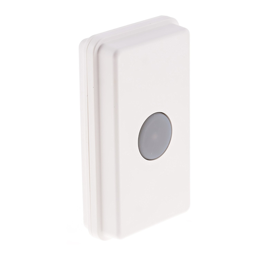
UT-2500
Universal
Transmitter
Owner's Manual
Warnings
This device complies with Part 15 of the FCC rules, Operation of
this device is subject to the following conditions: 1. This device
may not cause harmful interference. 2. This device must accept
any interference, including interference that may cause unde-
sired operation.
Introduction
The UT-2500 transmitter is compatible with the DCR-2500 receiv-
er. The UT-2500 has several methods of activation. First, it has a
push button that can be used as a panic button or doorbell. The
UT-2500 also has terminals for a normally open (N/O) or normally
closed (N/C) input. These inputs can be used with any detector
contacts. There is also a magnetic contact that can be used for
doors or windows. When the transmitter is activated, it will send a
signal to the receiver which will sound one of four different tones
(Classical, Westminster Chime, Ding Dong, or Whistle) for a few
seconds, or activate the relay outputs.
Operation:
(Always test unit prior to installation)
1. Remove the four screws on the back
of the case and open to find the battery
compartment and dip switches. (Figure
1)
2. Install the CR-2 battery in the holder
3. Set the dip switches 1-8 on the trans-
mitter module to match the receiver.
4. Set dip switches 9 and 10 to control
the desired zone, tune, and relay out-
put. (See Coding the transmitter for info
on setting the dip switches.)
Installing the battery:
1. Use only a CR-2, 3 Volt Lithium battery.
2. Be sure to observe proper polarity when installing the battery.
UT2500 manual.indd 1
LED indicator light in button:
1. The default setting is for the LED indicator to light up for two
seconds when the UT-2500 is activated.
2. To deactivate the LED, press and hold the push button while
installing the battery.
3. To return to the default LED setting remove the battery and
then re-install the battery.
Coding the transmitter:
1. Open the transmitter.
2. Locate the 10 dip switches in the transmitter
(Figure 2).
3. The first eight dip switches are for the fre-
quency setting (256 combinations). Set switches 1-8 to match the
eight switches in the receiver.
4. Switches 9-10 are for the zone/channel setting on the transmit-
ter. The four zones are as follows:
5. After any changes are made to the dip switches, the battery
must be disconnected and then reconnected for changes to take
effect.
Connecting an exterior detector:
The UT-2500 can be activated by
any type of detector which provides
a normally open (N/O) or normally
closed (N/C) output.
1. Locate the terminals at the bot-
tom of the case. (Figure 3)
2. Insert the wires through the sili-
cone gasket and make the connec-
tions on the terminals.
Note: a 22 AWG solid wire can be used
to easily pierce the silicone gasket. If
using a lighter wire you may need to
pierce the gasket with a paper clip or
small needle.
3. For a normally closed (N/C) connection, connect the wires to
(Figure 1)
the NC and Common (center) terminals.
4. For a normally open (N/O) connection, connect the wires be-
tween the NO and Common (center)terminals.
Switch
Switch
Channel
Tune
9
10
On
On
1
Classical
Off
On
2
Westminster
On
Off
3
Ding Dong
Off
Off
4
Whistle
(Figure 2)
TERMINALS
(Figure 3)
1/3/2013 4:18:50 PM
Advertisement

Related Manuals for Dakota Alert UT-2500


Summary of Contents for Dakota Alert UT-2500
- Page 1 Classical The UT-2500 transmitter is compatible with the DCR-2500 receiv- Westminster er. The UT-2500 has several methods of activation. First, it has a push button that can be used as a panic button or doorbell. The Ding Dong UT-2500 also has terminals for a normally open (N/O) or normally Whistle closed (N/C) input.
- Page 2 WARRANTY Mounting the transmitter: UT BACk COVER Dakota Alert warrants this product to be free of defects in mate- The transmitter can be mounted MOUNTINg rial and workmanship for a period of one year from the date of...