Table of Contents
Advertisement
Quick Links
Page 1
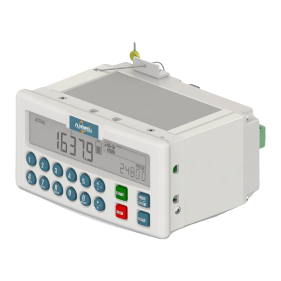
N414-P
panel mount BATCH-CONTROLLER
with NTEP certification and RECEIPT PRINTER DRIVER
Signal input flowmeter: Pulse – Coil, NPN, PNP, Reed, Namur, Active
Control input:
Five inputs for remote control.
Control output: Five outputs to control valves, pumps and alarms
Communication: Printer interface for receipt printing
FW-N414-P-M_v0203_01_EN.docx
Save time and cost with the user-friendly batch controller.
More info: www.fluidwell.com/nseries
Advertisement
Table of Contents

Subscribe to Our Youtube Channel
Related Manuals for Fluidwell N414-P


Summary of Contents for Fluidwell N414-P
- Page 1 Signal input flowmeter: Pulse – Coil, NPN, PNP, Reed, Namur, Active Control input: Five inputs for remote control. Control output: Five outputs to control valves, pumps and alarms Communication: Printer interface for receipt printing FW-N414-P-M_v0203_01_EN.docx Save time and cost with the user-friendly batch controller. More info: www.fluidwell.com/nseries...
-
Page 2: Safety Instructions
• If a company or individual makes changes to the N414-P to the extent that the metrological characteristics are changed, that specific device is no longer traceable to the NTEP Certificate of Conformance. -
Page 3: Intended Use
▪ appointed for the certification, the occupational, health, safety and the quality tasks. WARRANTY AND TECHNICAL SUPPORT For warranty and technical support for your Fluidwell products, visit our internet site www.fluidwell.com or contact us at support@fluidwell.com. -
Page 4: About The Operation Manual
This operation manual describes the standard unit as well as most of the options available. For additional information, please contact your supplier. A hazardous situation may occur if the N414-P is not used for the purpose it was designed for or is used incorrectly. Please carefully note the information in this operating manual indicated by the pictograms: A "warning"... -
Page 5: Table Of Contents
Target group ..........................3 Warranty and technical support ....................3 About the operation manual ......................4 Contents manual ......................... 5 Introduction .......................... 6 1.1. System description of the N414-P ................6 Operation ........................... 10 2.1. General ........................10 2.2. Custody transfer ......................10 2.3. -
Page 6: Introduction
The batch controller model N414-P is a microprocessor driven instrument designed for batching and of small and large batch size quantities. The batch controller N414-P is suitable for stationary wholesale custody transfer applications in the United States of America and is certified by NTEP. -
Page 7: Fig. 2: Display And Control Panel
24V DC. Configuration of the unit The N414-P was designed to be implemented in many types of applications. For that reason a SETUP menu is available to configure your N414-P according to your specific requirements. SETUP includes several important features, such as K-factors, measuring units, selection of the control outputs, receipt information, etc. -
Page 8: Fig. 3: Typical Identification Label
Up to 4 configurable headers Timestamp upon batch delivery Adjustable Tag number of unit number of blank rows Number of completed batches Delivered total Accumulated total Copy of original Not for resale ticket (config mode) Fig. 4: Typical printed receipts FW-N414-P-M_v0203_01_EN.docx... -
Page 9: Fig. 5: W&M Switch And Seal
W&M switch. It is also not possible to remove the N414-P from the cabinet panel. The certified lock-wire and the compression seal are not included in the scope of delivery and shall be provided and installed in accordance with the manufacturer’s instructions and... -
Page 10: Operation
2.1. GENERAL This chapter describes the daily use of the N414-P. This instruction is meant for users / operators. • The N414-P may only be operated by authorized and trained personnel. • All instructions in this manual are to be observed. -
Page 11: Operator Information And Functions
The N414-P is equipped with a smart – self learning – overrun correction: at the end of the process, the outputs will be switched-off earlier than the PRESET value is reached, taking the overrun quantity of previous batches into account. -
Page 12: Fig. 10: Example Display Information When Interrupted
Depending on the configuration settings, at the end of a completed or stopped batch: a) The N414-P prints a receipt automatically (AUTO). b) The N414-P shows the RECEIPT PUSH PRINT message. When you push the PRINT key, the receipt is printed (on confirmation). -
Page 13: Operator Alarms
▪ External alarm The N414-P can receive an external alarm during a batch. This can be set with SETUP 7.1 – Alarm. When the alarm is activated a running batch will be interrupted immediately and any other function will be blocked until the alarm status is cleared. -
Page 14: Installation
8. Set the Weights and Measures (W&M) switch to the operation position. 9. Commission the N414-P. 10. When the N414-P is successfully commissioned, install the security cap over the W&M switch and secure it with a certified lock-wire and a compression seal. -
Page 15: Mechnical Installation
Page 15 3.2. MECHNICAL INSTALLATION The N414-P has a mechanically secured, tamper-proof W&M switch to lock (by hardware) the setup menu. When set to the position, it is not possible to make changes to the settings. OPERATION 3.2.1. DIMENSIONS Fig. 11: Dimensions (Connector layout is a typical configuration) 3.2.2. -
Page 16: Preparation
(photo) and one on the bottom side. Use the supplied M4 x 6mm thread forming screw with a lock washer. On the top of the N414-P At the bottom of the N414-P Fig. -
Page 17: Voltage Selection Sensor Supply
Three basic types of flowmeter signals can be connected to the unit: pulse, active pulse or coil. The screen of the signal wire must be connected to the common ground terminal. The input signal type has to be selected with the correct SETUP-function (read par. 4.2.8.). FW-N414-P-M_v0203_01_EN.docx... -
Page 18: Fig. 16: Terminal Connections - Coil Signal Input (Typical)
Fig. 17: Terminal connections - Reed-switch signal input (typical) Namur: The N414-P is suitable for flowmeters with an Namur signal. The N414-P is able to power the Namur sensor, as an external power supply for the sensor is not required. -
Page 19: Fig. 19: Terminal Connections - Npn Signal Input (Typical)
Page 19 Pulse-signal NPN / NPN LP: The N414-P is suitable for use with sensors which have a NPN output signal. For reliable pulse detection, the pulse amplitude has to go above 1.2V. Signal setting NPN-LP employs a low-pass signal noise filter, which limits the maximum input frequency - read par. 4.2.8. -
Page 20: Fig. 22: Terminal Connections - External Start (Typical)
Terminal 11 can also be used to block the batch process: as long as this input is switched to Terminal 8, it is not possible to start a batch (the START button on the keyboard is blocked as well). Fig. 24: Terminal connections - External reset (typical) FW-N414-P-M_v0203_01_EN.docx... -
Page 21: Fig. 25: Terminal Connections - External Alarm (Typical)
Page 21 Terminal 8-12; External Alarm: With this function an external alarm release can be connected to the N414-P. A running batch will be interrupted immediately and will be blocked till the alarm status is initialized. Initialization is only accepted if the input is released. -
Page 22: Fig. 28: Terminal Connections - Mechanical Relay Output (Typical)
Max. Switching capacity (resistive load): 8A @ 250V AC / 30V DC. Max. Switching power (resistive load): 2000VA 240W. Note: The schematic diagram shows some typical applications to control a pump, a valve or an alarm. Fig. 29: Terminal connections - Mechanical controls output (typical) FW-N414-P-M_v0203_01_EN.docx... -
Page 23: Configuration
4.2.1. GENERAL Configuration of the N414-P is done at SETUP menu. SETUP menu is reached by pressing the PROG/ENTER key for 7 seconds; at which time, both arrows will be displayed. In order to return to the operator level, PROG will need to be pressed for three seconds. Alternatively, if no keys are pressed for 2 minutes, the unit will exit SETUP automatically. - Page 24 Alterations will only be set after ENTER has been pressed! To return to OPERATOR-level: In order to return to the operator level, PROG will have to be pressed for three seconds. Also, when no keys are pressed for 2 minutes, SETUP will be left automatically. FW-N414-P-M_v0203_01_EN.docx...
-
Page 25: Overview Functions Setup Level
8.8 ENDROW 0 – 9 8.9 FORMFEED enable – disable 8.A DATEFORMAT Y.M.D – D.M.Y – M.D.Y 8.B TOTAL Print, Skip 8.C SPEED 1200 – 2400 – 4800 – 9600 – 9600hp – 19200 – 38400 * Metrologically relevant parameter FW-N414-P-M_v0203_01_EN.docx... -
Page 26: Explanation Of Setup 1 - Preset
Page 26 9. OTHERS 9.1 MODEL N414-P 9.2 SW-VER (software version) XX.XX.XX 9.3 SERIAL NO. XXXXXXX 9.4 TIME xx:xx:xx (hh:mm:ss, 24 hr format) 9.5 DATE xx.xx.xx (format as per setup 8.6) 9.6 PASSWORD 0000 - 9999 9.7 KEY(BOARD) LOCK start – hold – preset – control – all – off 9.8 TAG-NR... -
Page 27: Explanation Of Setup 3 - Flowrate
EXPLANATION OF SETUP 4 - ALARM The N414-P offers a no-flow monitoring feature: When the flowmeter does not generate a signal during a certain (preset) time period, the N414-P will shut-off the control output(s) and bring the batch controller in alarm status. -
Page 28: Explanation Of Setup 6 - Flowmeter
EXPLANATION OF SETUP 6 - FLOWMETER *Below parameters are metrologically relevant thus mechanically secured with the W&M switch. The N414-P is able to handle high and low frequency pulses. Make sure to use the right terminal connection (see chapter installation). -
Page 29: Explanation Of Setup 7 - Control
With this function, it is determined if a pulse will be generated according to the quantity batched or according to accumulated total. With setting “batch” the pulse generator will be set to zero when a new batch is started and does not reflect the complete totalized volume. FW-N414-P-M_v0203_01_EN.docx... -
Page 30: Explanation Of Setup 8 - Printer
To select the print behavior after a batch is completed or stopped. PRINT AUTO: The N414-P automatically prints a receipt. ON CONF: The N414-P asks for an acknowledge (push PRINT) before printing the receipt. This setting is used to define the 16 character header text of the receipt. -
Page 31: Explanation Of Setup 9 - Others
4.2.12. CUSTODY TRANSFER SETTINGS The N414-P has a mechanically secured, tamper-proof W&M switch to lock (by hardware) metrologically relevant parameters in the setup menu. When set to the configuration position (unsecured), it is possible to make changes to these settings while indicator is shown. -
Page 32: Maintenance
(ANSI/NEDA 5020LC/AWCI L09), Lithium-Carbon/Fluoride, 3V/48mAh, Low-drain. 5.3. REPAIR POLICY If you have any problem with your Fluidwell product and you wish Fluidwell to repair it, please follow the procedure below: a. Obtain a Return Material Authorization (RMA) from your supplier or distributor Together with the RMA, you need to complete a repair form to submit detailed information about the problem. -
Page 33: Appendix A: Technical Specification
Frequency Minimum 0 Hz – maximum 10kHz for total and flowrate. Maximum frequency depends on signal type and internal low-pass filter. E.g. Reed switch with low-pass filter: max. frequency 120Hz. K-Factor 0.000010 – 9,999,999 with variable decimal position. Low-pass filter Available for all pulse signals. FW-N414-P-M_v0203_01_EN.docx... - Page 34 7 digits Units L – m3 – USGAL – IGAL – ft3 – bbl – kg –Ton – US Ton – lb Time unit /sec - /min -/ hour - /day Decimals 0 – 1 – 2 or 3 FW-N414-P-M_v0203_01_EN.docx...
-
Page 35: Appendix B: Problem Solving
Page 35 APPENDIX B: PROBLEM SOLVING In this appendix, several problems are included that can occur when the N414-P is going to be installed or while it is in operation. N414-P will not switch on, seems to have no power: Fuse blown ▪... -
Page 36: Appendix C: Declaration Of Conformity
Page 36 APPENDIX C: DECLARATION OF CONFORMITY FW-N414-P-M_v0203_01_EN.docx... -
Page 37: Index Of This Manual
Fig. 27: Terminal connections - Power supply mains (typical) ............21 Fig. 28: Terminal connections - Mechanical relay output (typical) ............. 22 Fig. 29: Terminal connections - Mechanical controls output (typical) ..........22 Fig. 30: Installing the security seal..................... 31 FW-N414-P-M_v0203_01_EN.docx... - Page 38 7. – CONTROL 7.1 batch relay 2 Batch 7.2 batch trans 1 Batch 7.3 batch trans 2 Batch 7.4 batch trans 3 Batch 7.5 preopen 0.0 sec. 7.6 preclose 7.7 width 0.000 sec 7.8 amount 1000 L 7.9 pulse Acc. Total FW-N414-P-M_v0203_01_EN.docx...
- Page 39 8.A dateformat YY:MM:DD 8.B total print 8.C speed 9600 9. - OTHERS 9.1 model N414-P N414-P N414-P 9.2 sw-version 03.03.xx 9.3 serial no. _ _ _ _ _ _ _ _ _ _ _ _ _ _ _ _ _ _ _ _ _ 9.4 time...
- Page 40 Page 40 Fluidwell B.V. PO box 6 Voltaweg 23 Website: www.fluidwell.com FW-N414-P-M_v0203_01_EN.docx 5460 AA Veghel 5466 AZ Veghel Find your nearest representative: www.fluidwell.com/representatives The Netherlands The Netherlands Copyright - 2017 - FW-N414-P-M_v0203_01_EN...
Need help?
Do you have a question about the N414-P and is the answer not in the manual?
Questions and answers