Advertisement
Quick Links
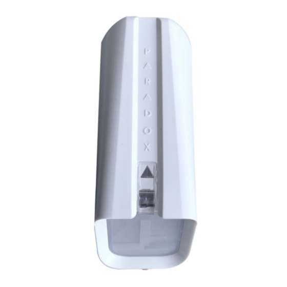
NV37M
Installation Manual V1.0
Outdoor/Indoor Window and Sliding Door
Dual Detector with Anti-Masking and
Pet Immunity
General Description
Thank you for choosing the NV37M for your professional protection
needs. The NV37M wired version will provide you the most advanced
window and sliding door protection either in Pet Immune or Sharp
mode. If you have any comments, please write to us at Paradox.com/
products/feedback.
Recommended Installations (please read)
Outdoor installation permits placements within frames of sliding
windows or doors and presumes protection from raindrops. This
ensures best catch performance, anti-masking ability, and pet alarm
immunity.
Other installations are possible but in outdoor conditions, pet immunity
can decrease. Moreover, space near the detector must be clear from
obstacles from a distance of 30 to 40 cm (11.8 to 15.7 in.) within its
pattern.
Installing the NV37M
1. Remove the NV37M front cover - open the Captive screw.
Front
cover
Captive screw
Figure 1 – Front Cover
Figure 2 – Main
2. Remove the Main Unit - open the two snap-lock mechanisms on
each side of the back cover attaching the Main Unit to the back
cover, then remove the Main Unit.
3. Pull the wires from the control panel through the knockout holes
and mount the back cover onto the window frame or wall using
screws.
Note: PLEASE KEEP AT LEAST 4 cm / 1.5 in. clearance from
window/shutter.
An optional mounting bracket for the NV37M is available for ordering,
part number: SB35.
4. Attach the Main Unit to the back cover - ensure the locks snap
closed.
5. Connect the wires to the terminal blocks according to the following
wiring assignment.
NV37M-EI00 07/2021
Knockout
holes
Mounting
screw
Tamper
knockout
hole
Tamper
screw
Figure 3 – Back Plate
Unit
4 cm /
1.5 in.
Table 1: Wiring Assignment
Terminal Connector
1
2
3
4
5
6
7
* Tamper must be enabled on SP panels.
6. Set the following Detector settings according to requirements.
Sensitivity Trimmer
LED flashes green 1-3
times according to the
selected level
Figure 4 – Detector Settings
The following table displays the Dip Switch settings.
Table 2: Dip Switch Settings
Dip Switch
Function
Number
1
LED
2
PET Immunity/
SHARP Mode
3
Anti-mask
4
Anti-mask
Sensitivity
7. Replace the front cover and close the Captive screw.
Note: Do not obscure the detector's field of view.
Testing the NV37M
Perform a Walk-Test to test successful installation:
1.
Walk slowly across the far end of the detection range.
2.
Ensure detection.
Walk test mode lasts 5 minutes after the tamper screw is closed.
Recommended Wiring Assignment
12V+
Minus (-)
Fault indication
Tamper* indication
Common (Fault & Tamper)
Alarm indication
Common (Alarm)
Mode Description
: LED on (default)
ON
: LED off
OFF
: PET Immunity mode (default)
ON
: SHARP mode
OFF
: On (default)
ON
: Off
OFF
: High (default)
ON
: Low
OFF
PARADOX.COM
Dip
Switch
Advertisement

Related Manuals for Paradox NV37M


Summary of Contents for Paradox NV37M
- Page 1 * Tamper must be enabled on SP panels. Thank you for choosing the NV37M for your professional protection needs. The NV37M wired version will provide you the most advanced 6. Set the following Detector settings according to requirements. window and sliding door protection either in Pet Immune or Sharp mode.
- Page 2 Limited Warranty Statement found on the website: www.paradox.com/ terms or contact your local distributor. Specifications may change without prior notice. Patents US, Canadian and international patents may apply. Paradox is a trademark or registered trademark of Paradox Security Systems (Bahamas) Ltd. NV37M-EI00 07/2021 PARADOX.COM...
Need help?
Do you have a question about the NV37M and is the answer not in the manual?
Questions and answers