Page 1
M 4 0 0 0 A d v a n c e d , M 4 0 0 0 A d v a n c e d A / P a n d M 4 0 0 0 A r e a 6 0 / 8 0 M u l t i p l e L i g h t B e a m S a f e t y D e v i c e AUDIN - 7 bis rue de Tinqueux - 51100 Reims - France - Tel : 03.26.04.20.21 - Fax : 03.26.04.28.20 - Web : http: www.audin.fr - Email : info@audin.fr...
Page 2
This document is protected by the law of copyright, whereby all rights established therein remain with the company SICK AG. Reproduction of this document or parts of this document is only permissible within the limits of the legal determination of Copyright Law. Alteration or abridgement of the document is not permitted without the explicit written approval of the company SICK AG.
Safety Data Link = SICK safety interface (connection for OSSD and EFI of an ESPE) Symbols used Recommendations are designed to give you some assistance in your decision-making Recommendation process with respect to a certain function or a technical measure.
All warranty claims against SICK AG are forfeited in the case of any other use, or alterations being made to the system, even as part of their mounting or installation.
Page 14
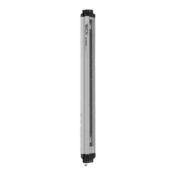
M4000 Advanced The M4000 Advanced multiple light beam safety device is available with 2, 3 or 4 beams. Other configurations with up to 12 beams are possible on request. The maximum scanning range (dimension of the light path between sender and receiver) is 70 m.
(see chapter 4.4 “Scanning range” on page 24ff). • You can extend the M4000 Advanced A/P multiple light beam safety device with a maximum of one deflector mirror. Controls and status indicators The LEDs and the 7@segment display of sender and receiver signal the operating status of the M4000.
The person who makes the change is also responsible for the correct protective function of the device. When making configuration changes, please always use the password hierarchy provided by SICK to ensure that only authorised persons make changes to the configuration. The SICK service team is available to provide assistance if required.
• After switching on, the 7@segment display of sender and receiver will briefly display the coding. Device symbol M4000 Advanced (sender or receiver), M4000 Advanced (A/P) or M4000 Area (sender or receiver), context menu Open device window, parameter node General.
4.4.1 Scanning range of the M4000 Advanced You can set the M4000 Advanced multiple light beam safety device to two different scanning ranges. The effective scanning range is dependent here upon the dimension of the light path between sender and receiver and the number of deflector mirrors and additional front screens used.
Device symbol M4000 Advanced (A/P), context menu Open device window, parameter node General. The maximum effective scanning range is dependent here on the number of deflections between the M4000 Advanced A/P and the M4000 Passive and the number of additional front screens used (see Tab. 9). Number of...
Chapter 4 M4000 Adv., Adv. A/P, Area Sender test The function Sender test is not available with the M4000 Advanced A/P. Note The M4000 sender has a test input on pin 3 for checking the sender and the related receiver. During the test, the sender no longer emits light beams.
(see section 12.7 “Accessories” on page 98). • If you do not use either a SICK switching amplifier or a SICK bus node on the system connections pin 9 and pin 10 (EFI device communication), to improve the EMC behaviour we recommend —...
(see section 12.7 “Accessories” on page 98). • If you do not use either a SICK switching amplifier or a SICK bus node on the system connection pin 9 and 10 (EFI device communication), to improve the EMC behaviour we...
Pin 3 0 V DC (voltage supply) Pin 5 Pin 2 The pin assignment of sender, receiver and M4000 Advanced A/P is identical. Note After configuration always remove the connecting cable from the configuration connection! After the configuration of the device has been completed, locate the attached protection cap to cover the configuration connection.
• If you use the application diagnostic output as an alarm signal for “Reset required”, it has a frequency of 1 Hz. • Only M4000 Advanced and M4000 Advanced A/P in conjunction with external switching amplifier, e.g. UE403: If you connect the application diagnostic output as an alarm signal for muting or override status, then the application diagnostic output will always signal the alarm with an active HIGH.
The sender test is performed when 0 V is present at the test input (pin 3) of the sender. To be able to use the sender test button, you must also configure the Sender test function with the aid of the CDS: Device symbol M4000 Advanced (sender), context menu Open device window, parameter node General.
(each mirror on the mirror columns must be adjusted). The following alignment aids are available: • integrated laser alignment aid per beam (optional, only for M4000 Advanced) On this subject read the description in chapter 7.2.4 “Alignment of the M4000 Advanced with integrated laser alignment aid (optional)”...
Switch the power supply to the multiple light beam safety device on. Watch the alignment information on the 7@segment display of the receiver. Correct the alignment of the sender and receiver (or of the M4000 Advanced A/P and the M4000 Passive), until the 7@segment display goes off.
The M4000 Advanced multiple light beam safety device is available with an integrated laser alignment aid as an extra. The laser alignment aid in conjunction with the indications on the 7@segment display enables you to precisely adjust and align the multiple light beam safety device.
Page 57
2 minutes. – independent of the state after 60 minutes. • In the delivery with the receiver for the M4000 Advanced with integrated laser alignment aid you will find two self-adhesive alignment templates (one template for the deflector mirror and one for the sender).
Page 62
– immediately in front of the M4000 Advanced A/P – in the middle between M4000 Advanced A/P and M4000 Passive or another mirror deflection (e.g. deflector mirror PSK45) – immediately in front of the M4000 Passive or another mirror deflection (e.g. deflector mirror PSK45) –...
Static charges cause dust particles to be attracted to the front screen. You can prevent Note this effect by using the antistatic plastic cleaner (SICK Part No. 5600006) and the SICK lens cloth (SICK Part No. 4003353). How to clean the front screen: Use a clean and soft brush to remove dust from the front screen.
Page 74
The external voltage supply must be capable of buffering brief mains voltage failures of 20 ms as specified in EN 60 204-1. Suitable power supplies are available as accessories from SICK (Siemens type series 6 EP 1). Within the limits of V Only with Active/Active systems.
Page 83
1035 1064 If you use a two-beam M4000 Advanced A/P, then instead of the M4000 Passive you can Note use one of the following alternatives: • two deflector mirrors PSK45 (see section 11.3.9 “Deflector mirror PSK45” on page 89) •...
±0.5 73.5 (61) Part No. 5306053 • If you use a two-beam M4000 Advanced A/P, then you can use two PSK45 deflector Notes mirrors instead of the M4000 Passive. • The deflector mirror PSK45 is not suitable for column mounting.
Chapter 13 Operating Instructions M4000 Adv., Adv. A/P, Area 13.3 Alignment templates For the alignment of the M4000 Advanced with integrated laser alignment aid you need two alignment templates: • alignment template for mirrors • alignment template for the sender The alignment templates are in the delivery of the M4000 receiver .
Tab. 6: Possible configuration for the application diagnostic output ....... 24 Tab. 7: Scanning range of the M4000 Advanced as a function of the number of deflections per beam and the additional front screens........25 Tab. 8: Scanning range of the M4000 Advanced A/P to be configured dependent of the deflector unit used ..................
Tab. 37: Type codes M4000 Advanced with M26 plug and integrated alignment aid..........................91 Tab. 38: Type codes M4000 Advanced with M26 plug and end cap with integrated LED ...........................91 Tab. 39: Type codes M4000 Advanced with M26 plug, integrated alignment aid and end cap with integrated LED ................91...
Page 108
M4000 Adv., Adv. A/P, Area Fig. 12: Status indicators of the sender................19 Fig. 13: Status indicators of the receiver or of the M4000 Advanced A/P ....... 20 Fig. 14: Schematic illustration of the protective operation..........21 Fig. 15: Schematic illustration of the beam coding............23 Fig.
Need help?
Do you have a question about the M4000 Advanced and is the answer not in the manual?
Questions and answers