Table of Contents
Advertisement
Quick Links
Model 8310-2410
The product warranty will be voided if the product is mounted for an exterior door and/or is exposed to elements.
Description
Actuators
Available faceplates:
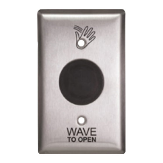
Double Gang "Wave to Open" actuator with light ring
Double Gang "Wave to Open" actuator without light ring
Single Gang "Wave to Lock" actuator with light ring
E-strike
Provided faceplates:
•
4-7/8" x 5/8" (ANSI Square/Hollow Metal)
•
6-7/8" x 5/8" (Aluminum)
•
7-7/8" x 5/8" (Wood Door)
Parts lists
Main parts list
Item
#
1
"Wave to Open" Switch w/o Light Ring
2
"Wave to Open" Switch w/ Light Ring
3
"Wave to Lock" Switch
4
Power Supply/Relay Cabinet
5
Door position switch
E-strikes parts list
Item
#
E-strike (comes pre-installed w/ ANSI
1
faceplate)
2
Aluminum faceplate
3
Wood faceplate
4
Faceplate template
5
24V female connector
6
Varistor (MOV)
7
Trim plate
8
Mounting brackets
9
Wire nuts
#10-32 x 1/2" machine screws
10
(installed w/ ANSI faceplate on
e-strike)
#10 - 11/4" wood screws (for mounting
11
brackets)
M5 x 12mm machine screws (for
12
mounting brackets)
For cleaning purposes, do not expose components to extreme wash-down.
The electric strike is not water-proof.
Description
Description
8310-2410 Touchless Restroom Kit
CAUTION
•
Transformer
•
Open style, channel bracket, two-hole chassis mount.
•
120 VAC @ 60 Hz.
•
Minimum 6" leads
•
Class B insulation (130° C)
Cabinet
•
11 /16" x 7 7/8" x 2 11/16"
•
Power supply (blue circuit board), Relay Module (green
circuit board), and two terminal buses.
•
Must be set to 24VDC output
Item
Quantity
#
Vinyl Plaque "Door locked when red/
1
6
unlocked when green"
1
Vinyl Plaque "Door occupied when
7
red/vacant when green"
1
8
E-Strike w/ 3 faceplates
1
9
Transformer
1
Quantity
1
1
1
3
1
1
1
2
4
2
2
5
Installation Instructions
Description
Quantity
1
1
1
1
Advertisement
Table of Contents

Related Manuals for LCN 8310-2410


Summary of Contents for LCN 8310-2410
- Page 1 8310-2410 Touchless Restroom Kit Model 8310-2410 Installation Instructions CAUTION The product warranty will be voided if the product is mounted for an exterior door and/or is exposed to elements. For cleaning purposes, do not expose components to extreme wash-down. The electric strike is not water-proof.
-
Page 2: Technical Specifications
Technical specifications Actuators Actuators with light ring Actuator without light ring (Outside Wave to Open/Inside Wave to Lock) (Inside Wave to Open) No. of IR sensors Body size 4” x 1” x 1 1/2” Operating voltage 12 - 24 volts, AC/DC ± 10% Mounting 2 x #6-32 MS Faceplates... -
Page 3: Operation At A Glance
Transformer Descriptions 8310-2410 Series Input voltage 120V AC Output voltage 24V AC @ 60 Hz Class Power 50 VA DPS Switch Descriptions 8310-2420 Series Power max. 3.0 W Electrical configuration SPDT Suggested Wiring 22AWG Gap distance max. 0.75” Operation at a glance When the outside WAVE TO OPEN touchless switch is activated it will trigger its N.O. - Page 4 Single gang box mount Label Label Label Label Wall Wall Wall Wall Double gang box mount Surface Mount Enclosure Label Gasket #6-32 x 3/4” (2 Pcs) IR Lens Faceplate Faceplate #6-32 x 1/2” (2 Pcs) Polypropylene Lens Holder Set Adapter Plate Wall Faceplate Gasket...
- Page 5 Note: The products are intended to be installed in accordance with the installation wiring diagram, mechanical assembly drawings provided with each product, the local authority having jurisdiction (AHJ) and the National Electric Code, NFPA 70. When installed in fail secure mode, the local authority shall be consulted with regard to the use of possible panic hardware to allow emergency exit from the secure area.
-
Page 6: All Applications
All applications The 8310-2410 comes with the relay module pre-wired to a labeled set of two terminal strips. A complete wiring diagram is adhered to the inside of the door to provide a layout of the wiring as a reference when wiring the field devices to the kit. -
Page 7: Actuator Wiring
2 5 8 '' 3 3 4 '' Ă 1 [66.68mm] [93.73mm] 8 '' 2 1 8 '' [25.40mm] [3.81mm] [55.50mm] [78.48mm] 1 7 8 '' 2 1 4 '' 8 '' 1 3 4 '' 2 1 4 '' 1 3 8 '' [47.63mm] [55.88mm]... - Page 8 E-strike A varistor is provided to protect/prevent strike from spikes. Connect varistor between input wires. Power L The 24V Black and Female Red wires from the Connector Red wire female connector will (+24V) wire to the VDC+ and Black Varistor VDC- terminals in the Blue Power Supply/Relay...
- Page 9 Set-up L NOTE: The red dip switches (power supply dip switches) need to be set for 24V. - Dip switch SW1 should be set to OFF - Dip switch SW2 should be set to ON All applications flashing) will be how long relay 1 will be activated for (0-50 Selecting a Mode seconds).
- Page 10 TB3-5 Inputs Terminal Function Description TB3, Terminals A dry contact closure across these inputs will activate the Request to Exit 1 & 2 relay(s) as per their settings. TB4, Terminals Door Contact Normally closed, Used for Security Mode 1 & 2 TB5, Terminals External light ring control.
- Page 11 DIP switch 3 – Light ring DIP switch IDLE ACTIVE No Color No Color Green Blue Blue Green Green All OFF Blue Blue Green Blue DIP 1 SW4 – External Light Ring Control ON = Enabled, OFF – Disabled When SW4 is ON, the light ring changes color according to the above table but will follow the state of the External Input on TB5.
- Page 12 Momentary When an object is in range of the sensor, the actuator operates momentarily. It will not operate again until the object is removed and presented again. If the object remains in range of the sensor, no alarms are generated. Momentary with Alarm When an object is in range of the sensor, the actuator operates momentarily.
- Page 13 Switch 3 – LED On/LED Off This switch disables the LED, should this feature be desired. Factory setting is ON. Once the Dip switches have been set, and the unit is installed in the frame or enclosure, apply power to the unit and observe operation.
- Page 14 Restroom signage INSIDE THE RESTROOM WAIT FOR DOOR TO CLOSE USE ''WAVE TO LOCK'' SWITCH TO LOCK THIS DOOR LOCKED WHEN RED UNLOCKED WHEN GREEN Indicator on switch will turn red when door is locked. WAVE WAVE TO OPEN TO LOCK Place Sign On The Door Inside The Restroom...
- Page 15 Wiring diagram GREEN BLUE...
- Page 16 Cabinet base template 6" 9⁵⁄8"...
-
Page 17: Troubleshooting
Auto Operator Wiring Auto operator 4630/4640 Series Electric Auto- Terminals 17 or 19 Terminals 16 or 18 Equalizers 7900 Series Pneumatic Auto- Terminal 10 Terminal 8 (for Door A) or Equalizers Terminal 6 (for Door B) 9100 Series Benchmark Either “MAIN ACT” terminal Either “MAIN ACT”... - Page 18 Scenario Cause Solution Electric Strike itself is set to Follow the electric strike instructions in the Set-up section to change Fail Secure rather than Fail the screw on the back of the strike from Fail Secure to Fail Safe. Safe. The strike needs to be in the closed position in order for the strike to Strike is not fully seated/ in lock.
- Page 19 E-strike (Fail Secure mode) Scenario Cause Solution In Relay Module, press “Menu” button until an “M” appears in the left Logic Module not in Mode “M 8” of the display. Press the “up” and “down” buttons until the display reads “M 8.” Verify continuity from female e-strike connector pins to e-strike +/- terminals.
- Page 20 Automatic operator Scenario Cause Solution Automatic Door will not mechanically Verify electric strike installation and ensure other door hardware is operator will not open not preventing the door from opening. open Operator issue Disconnect the two activation wires going from the operator to the "Door Operator"...
- Page 21 Scenario Cause Solution Restroom Kit provides Voltage issue with transformer Verify Actuator has correct voltage (~27VDC, ~0 VAC) unwanted or relay cabinet actuation Actuator light ring Scenario Cause Solution Verify wires from VDC +/- Control terminals are going to TB6 +/- No power to the actuator terminal on both actuators.
- Page 24 © Allegion 2022 Printed in U.S.A. 47558233 Rev. 05/22-b...
Need help?
Do you have a question about the 8310-2410 and is the answer not in the manual?
Questions and answers