Table of Contents
Advertisement
*740158*
740158
Swing Operator
Models 9130, 9140 & 9150
General .....................................................................................................................................................................................................1
Replacement Parts & System Components .............................................................................................................................................1
Replacement Parts & System Components (Cont.) .................................................................................................................................2
1 Pre-Installation Site & Product Check....................................................................................................................................................3
2 Operator Installation ..............................................................................................................................................................................4
3 Wiring.....................................................................................................................................................................................................7
4 Arm & Cover Installation ........................................................................................................................................................................7
5 Operational Check .................................................................................................................................................................................9
6 Operator Adjustment ............................................................................................................................................................................10
7 Release for Service ............................................................................................................................................................................. 11
8 Benchmark III Software ....................................................................................................................................................................... 11
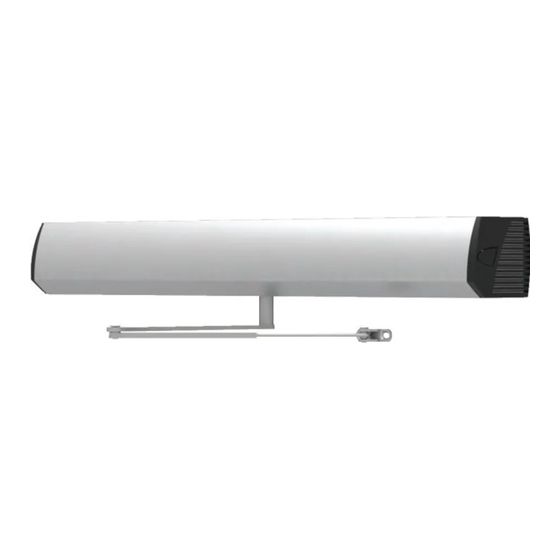
The Benchmark is an automatic electromechanical swinging door operator for use on hinged, center pivoted and offset pivoted doors.
When activated, the Benchmark drives the door to full open position, then electrical power is turned off and the door is closed by spring
force. The activating circuit opens the door from any position in the closing swing. During a power failure, the Benchmark acts as a
manual door closer (Size 3). Door opening and closing cycles, including opening speed, back check speed, hold open time delay, closing
speed, and latch position, are adjustable.
always disconnect main power to the operator prior to
servicing or cleaning.
Part
Premium Control
Box
Gear Box
End Caps
Part
Arm Assembly
Benchmark III
Warning
Replacement Parts & System Components
27" Header
9130-3462SC
9140-3462SC
9130-3454S
9140-3554S
9130-334
Pull
9130-3077T
Table of Contents
General
this operator is for indoor use only.
Do not mount any accessories directly to the operator.
Full Length Header
Single
9130-3462SC
9150-3462SC
9140-3462SC
9130-3454
9150-3454S
9140-3454
9140-334
9150-334
Standard Push
reveal Push
9140-3077
9140-3077L
9150-3077
9150-3077L
Installation Instructions
Caution
Full Length Header Double
Extended
Finish
US28
DC13
Advertisement
Table of Contents

Subscribe to Our Youtube Channel
Related Manuals for LCN Benchmark III 9140


Summary of Contents for LCN Benchmark III 9140
-
Page 1: Table Of Contents
*740158* Benchmark III 740158 Swing Operator Installation Instructions Models 9130, 9140 & 9150 Table of Contents General ........................................1 Replacement Parts & System Components .............................1 Replacement Parts & System Components (Cont.) ..........................2 1 Pre-Installation Site & Product Check..............................3 2 Operator Installation ....................................4 3 Wiring........................................7 4 Arm &... -
Page 2: Replacement Parts & System Components (Cont.)
Replacement Parts & System Components (Cont.) Double Push System (Screw pack not shown) -
Page 3: Pre-Installation Site & Product Check
Pre-Installation Site & Product Check Check that the Product Model is correct for the required application. Check that all parts listed on the Bill of Material are in the shipping container. Check the architectural drawings and final approved shop drawings for the position of frame and structural openings. Check header and frame dimensions and required clearances. -
Page 4: Operator Installation
Operator Installation Remove Control Box from Operator Mounting Bracket, then remove Motor/Gearbox from Bracket: Control Box and Motor/gearbox removal 27” Pull, 27” Push, and Double Push Systems Control Box and Motor/gearbox removal Full Length Pull and Full Length Push Systems Prepare Header/Frame and Door: a. -
Page 5: 27" Pull System
27” Pull System Header/Frame and Door Preparation Full Length Pull System Header/Frame and Door Preparation Center Operator Cover (with End Caps removed) over opening and mark a vertical line at each end. Align ends of Operator Mounting Bracket and Switch Bracket with vertical lines and adjust vertical position per diagram below. Mark and prepare mounting holes. 27”... -
Page 6: Full Length Push System
Full Length Push System Frame/Header and Door Preparation Center operator cover (with end caps removed) over opening and mark a vertical line at each end. Align ends of operator mounting bracket and switch bracket with vertical lines and adjust vertical position per diagram below. Mark and prepare mounting holes. Double Push System Header/Frame and Door Preparation Center operator cover (with End Caps removed) over opening and mark a vertical line at each end. -
Page 7: Wiring
Low Ceiling application (27” Push System only) Header/Frame and Door Preparation Wiring Caution Make sure all wires are properly dressed and secured to prevent interference. route all wiring away from moving parts, sharp edges, and heat sources. use copper conductors only. Do not modify the factory wiring or connect into existing electrical circuits or devices. - Page 8 Attach the arm to the operator spindle loosely with the 8mm socket head screw. For push systems, ensure that the adjusting boss is inserted correctly. Attach the arm to the door. 1. For push systems, attach the push arm shoe to the door: 2.
-
Page 9: Operational Check
3. Keep the door in the full open position and adjust the arm length as necessary to align the door at 90 degrees from closed. When the arm is adjusted to the correct length, tighten the 8mm socket head screw that secures the arm to the operator spindle. 4. -
Page 10: Operator Adjustment
Operator Adjustment See table below and diagrams (page 16) for operator feature adjustment. After adjusting, cycle the door several times to check for proper operation. Then continue with step 4k on page 9. notE adjust operator for the SLoWESt operation practical, in accordance with the latest revisions of the americans with Disabilities act (aDa);... -
Page 11: Release For Service
Release for Service Remove all tools, installation equipment and debris from the vicinity of the door. MANDATORY: Install all Safety, Traffic Control and Instruction Labels onto the door, as required. Failure to do this will leave the INSTALLER LIABLE for any accidents that occur. Give verbal instruction on how to properly operate the door to the owner or person in charge. - Page 12 For clarity, not all components are shown on the control box PC board J8, 10-position Control Box Power Cable J1, 6-position Main Power Cable J5, 2-position Motor Power Cable J3, 4-position Hall Effect Cable Plug cables into these receptacles Control box grounding stud Black DC- Electric Lock,...
- Page 13 8.500 4.25 Front FRONT 11.000 11.000 BEGINNING SHEET FOlDED SHEET Additional Notes: Revision History Revision Description: E > New Release 1. None 042801 Material Edited By Approved By EC Number Release Date White Paper D. Myers M. Sasso 042801 01-01-14 Notes Title 1.
Need help?
Do you have a question about the Benchmark III 9140 and is the answer not in the manual?
Questions and answers