Table of Contents
Advertisement
Quick Links
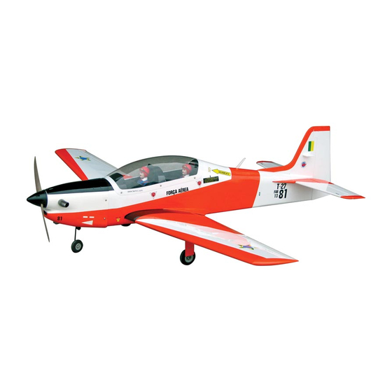
TUCANO 60
0.55 cubic inch displacement 2-stroke
0.91 cubic inch displacement 4-stroke
Requires : 7-channel radio w/ 6 standard servos
Wing Span
Wing Area
Flying Weight
Fuselage Length
and 2 low profile retract servos.
63 in / 1600 mm
627.8 sq in / 40.5 sq dm
7.2 ~ 7.6 lbs / 3290 ~ 3440 g
54 in / 1370 mm
INSTRUCTION MANUAL
Advertisement
Table of Contents

Subscribe to Our Youtube Channel
Related Manuals for The World Models Manufacturing TUCANO 60


Summary of Contents for The World Models Manufacturing TUCANO 60
- Page 1 INSTRUCTION MANUAL TUCANO 60 0.55 cubic inch displacement 2-stroke 0.91 cubic inch displacement 4-stroke Requires : 7-channel radio w/ 6 standard servos and 2 low profile retract servos. Wing Span 63 in / 1600 mm Wing Area 627.8 sq in / 40.5 sq dm Flying Weight 7.2 ~ 7.6 lbs / 3290 ~ 3440 g...
-
Page 2: Before You Begin
TUCANO 60 I N D E X BEFORE YOU BEGIN P. 1 P. 2 PARTS LIST P.3-P.12 ASSEMBLY SAFETY PRECAUTIONS P.13 BEFORE YOU BEGIN Read through the manual before you begin, so you will have an overall idea of what to do. - Page 3 Parts List WASHER d4xD9mm -- 4 pcs 1. MAIN WING -- 1 pair ENGINE MOUNT PL5111070 -- 1 set WOOD 7x16x76mm (For Engine Mount) -- 2 pcs 2. RETRACTABLE LANDING GEAR -- 1 pair RETRACTABLE LANDING GEAR COVER -- 1 pair 12.
-
Page 4: Aileron Servo
Main Wing Apply instant type CA glue to both sides of each hinge. Lead to Aileron Servo KA 3x14mm Main Landing Gear Pre-install Bottom View Retractable Landing Gear Cover PM2x6mm Screw M2 Nut d2xD5mm Washer PM2x6mm M2 Nut d2xD5mm Washer Bottom View Ø1mm pilot holes for World Models tri-horn are pre-drilled. - Page 5 Please dry fit wing joiner into left and right wing to make sure they fit with the Main Wing proper dihedral angle, mark the wing joiner if necessary. Apply epoxy glue to both sides of all surfaces in contact. Use a stick to apply the glue to inner side of wing joiner sleeve, and apply the glue to wing joiner before putting them together.
-
Page 6: Stabilizer & Elevator
Apply instant type CA glue to both sides Stabilizer & Elevator of each hinge. (Stabi l i zer) (Mai n Wi ng) B=B' A=A' Temporary install the main wing, adjust leveling of the stabilizer to make it as parallel to the main wing as possible Balsa 8x25x105.6mm Completed Vertical Fin &... -
Page 7: Elevator Pushrod
Elevator Pushrod Ø1m m pilot holes for Wor ld Models tr i-hor n ar e pr e-dr illed. Please look for pin-hole m ar ks at under side of contr ol sur faces. PB2x14mm Screw PB2x14mm Fuel Tube 72mm Ø6x5mm 170mm Elevator Pushrod Tri-horn... -
Page 8: Engine Mount
Apply thread locker to screws Engine Mount M4x30mm Socket Head Screw Wood 7x16x76mm d4xD9mm Washer Socket Head Screw M4x30mm d4xD9mm Washer Engine Mount Blind nuts are off-centered to keep PL5111070 Bottom View the spinner at the fuselage axis. Fuel Tank Fuel Tank Setup 380cc Fuel Tank... - Page 9 Engine M4x30mm Socket Head Screw d4xD9mm Washer M4 Nut M4x30mm Socket Head Screw Installed Engine Position 145 - 148mm 5.7 - 5.83in d4xD9 Washer Throttle Pushwire Plastic Tube M4 Nut Ø1.2x435mm d2xD3x230mm Bottom View Cowling Please refer to the attached sheet for usage of the transparent PWA2.6x10mm Screw 3D template.
- Page 10 Canopy First insert the grommet to the canopy then apply screw. PWA2.3x8mm Screw d1.5xD6.5mm Silicon Grommet Front Instrument Panel Decals Decals Pilot Seat Silicom Grommet PWA2.3x8mm d1.5xD6.5mm Servo Set 3x3mm Set Screw 3x 3mm Set Screw Linkage Connector Throttle Pushwire M2 Nut Washer 2mm Washer...
-
Page 11: Radio Equipment
Radio Equipment Install and arrange the servo as shown in the diagram. J1(Pushrod Ø1.8x80mm) A.Servo and battery setup for 2C.0.55 light engine. Rudder Pushrod Nose Retract Pushrod Throttle Servo Nose Wheel Rudder Servo Steering Pushrod Plastic Tube J2(Pushrod Ø1.8x610mm) d3.5xD5.2x240mm Fuel Tube Receiver Ø6x5mm... - Page 12 Wing Setting Adjust the wing and fuselage configuration as shown in the diagrams. A=A' B=B' C=C' D=D' P.11...
-
Page 13: Control Throws
Control Throws Adjust the control throws as shown in the diagram. These throws are good for general flying. You can adjust according to your personal preference. Elevator 17mm 17mm Rudder 30mm 30mm Flaps (near fuselage) 20mm Aileron 13mm 13mm C.G. The ideal C.G. - Page 14 Pre - flig h t ad ju stm en t m u st b e d o n e b efo re flyin g , it is very d an g ero u s to fly a b ad ly pre - ad ju sted aircraft. TUCANO 60 is specially designed to be powered by 2C 0.55 or 4C 0.91 engine, using a more powerful engine does not mean better performance.
- Page 15 Usage of the transparent 3D template This transparent 3D template is used for position guidance of the actual cutting of the pre-painted cowling. Simply cut the transparent 3D template to fit your engine and exhaust pipe, then slide onto the actual cowling and use as template to mark the openings required for final cutting.
-
Page 16: Optional Parts ( Accessories)
Optional Parts ACCESSORIES) 180mm Extension Fuel Filler Code No. Size Package Code No. Size Package KW0011800 PL8110030 180mm 1 set 15 x 22 x 49mm 1 x 1 pc 180mm Y-Cord Code No. Size Package KW0021800 180mm 1 pc Clevis Wrench Code No. - Page 17 http://www.theworldmodels.com A274PO20260905...
Need help?
Do you have a question about the TUCANO 60 and is the answer not in the manual?
Questions and answers