
Subscribe to Our Youtube Channel
Related Manuals for Allied Telesis ANC10 Series


Summary of Contents for Allied Telesis ANC10 Series
- Page 1 ANC10 Series 10 Gigabit Network Interface Cards ANC10Sa/2 ANC10T/2 Installation and User’s Guide 613-003027 Rev. A...
- Page 2 Allied Telesis, Inc. has been advised of, known, or should have known, the...
- Page 3 European Union Restriction of the Use of Certain Hazardous Substances (RoHS) in Electrical and Electronic Equipment This Allied Telesis RoHS-compliant product conforms to the European Union Restriction of the Use of Certain Hazardous Substances (RoHS) in Electrical and Electronic Equipment. Allied Telesis ensures RoHS conformance by requiring...
- Page 4 RFI Emissions FCC Part 15, EN55032 Class B, VCCI Class B, ICES-003 Immunity EN55035, EN 61000-3-2, EN 61000-3-3 Electrical Safety EN62368-1 (TUV), UL 62368-1 ( S), CSA C22.2 No. 62368-1 Environmental RoHS Laser Safety EN60825...
- Page 5 Translated Safety Statements Important: Safety statements that have the symbol are translated into multiple languages in the Translated Safety Statements document at www.alliedtelesis.com/library. Remarque: Les consignes de sécurité portant le symbole sont traduites dans plusieurs langues dans le document Translated Safety Statements, disponible à l'adresse www.alliedtelesis.com/ library.
-
Page 7: Table Of Contents
Contents Preface ................................13 Safety Symbols Used in this Document .....................14 Contacting Allied Telesis..........................15 Chapter 1: Introduction ..........................17 Functional Description..........................18 ANC10Sa/2 Network Interface Card SFP+ Ports..................19 ANC10T/2 Network Interface Card Twisted Pair Copper Ports ..............22 Features ..............................24 Software ..............................25 Chapter 2: Installing the Hardware ......................27 Reviewing Safety Precautions ........................28... - Page 8 Contents Maximum Number of RSS Processors...................... 73 Maximum Number of RSS Queues ......................74 Maximum RSS Processor Number......................75 Network Direct Functionality........................76 Network Direct Technology ........................77 NVGRE Encapsulated Task Offload......................78 Packet Direct ............................. 79 Preferred NUMA Node ..........................80 Priority &...
- Page 9 Figures Figure 1: ANC10Sa/2 Network Interface Card........................20 Figure 2: ANC10Sa/2 Network Interface Card Faceplate....................20 Figure 3: ANC10T/2 Network Interface Card........................22 Figure 4: ANC10T/2 Network Interface Card Faceplate ...................... 22 Figure 5: Removing the Low-profile Bracket........................31 Figure 6: Installing the Standard Bracket..........................32 Figure 7: Software Downloads Window..........................
- Page 10 List of Figures Figure 50: RoCE MTU Window............................91 Figure 51: RSS Base Processor Group Window ......................... 92 Figure 52: RSS Base Processor Number Window ......................93 Figure 53: RSS Load Balancing Profile Window........................94 Figure 54: RSS Max Processor Group Window........................96 Figure 55: Software Timestamp Window ..........................
- Page 11 Tables Table 1. ANC10 Network Interface Card Series .........................18 Table 2. ANC10Sa/2 LED Status ............................21 Table 3. ANC10T/2 Link and Activity LEDs ........................23 Table 4. Physical Specifications ............................121 Table 5. Environmental Specifications ..........................122 Table 6. Operating Voltages and Maximum Power Consumption ..................122 Table 7.
- Page 12 List of Tables...
-
Page 13: Preface
Network Interface Card Series. The Preface discusses the following topics: “Safety Symbols Used in this Document” on page 14 “Contacting Allied Telesis” on page 15 This guide contains the installation instructions for the following dual 10G port Network Interface Cards (NICs): ANC10Sa/2 ... -
Page 14: Safety Symbols Used In This Document
Preface Safety Symbols Used in this Document This document uses the following conventions: Note Notes provide additional information. Caution Cautions inform you that performing or omitting a specific action may result in equipment damage or loss of data. Warning Warnings inform you that performing or omitting a specific action may result in bodily injury. -
Page 15: Contacting Allied Telesis
guides, software release notes, white papers and data sheets for your product. Warranty - View a list of products to see if Allied Telesis warranty applies to the product you purchased and register your warranty. Allied Telesis Helpdesk - Contact a support representative. - Page 16 Preface...
-
Page 17: Chapter 1: Introduction
Chapter 1 Introduction This chapter provides an introduction to the ANC10 Series network interface card and discusses the following topics: “Functional Description” on page 18 “ANC10Sa/2 Network Interface Card SFP+ Ports” on page 19 “ANC10T/2 Network Interface Card Twisted Pair Copper Ports” on ... -
Page 18: Functional Description
CAT5e or CAT6A or better Note The maximum operating distance of the SFP+ ports on the ANC10Sa/2 network interface card depends on the transceivers. Refer to the product's data sheet on the Allied Telesis web site for a list of supported transceivers. -
Page 19: Anc10Sa/2 Network Interface Card Sfp+ Ports
SFP+ transceiver and type of fiber optic cabling. The ports support the following types of transceivers: Note See the Allied Telesis website for supported SFP+ models. 1Gbps short and long distance SFP transceivers using multi-mode or single mode fiber optic cable. -
Page 20: Figure 1: Anc10Sa/2 Network Interface Card
SFP+ transceivers must be purchased separately. For a list of supported transceivers, refer to the product's data sheet on the Allied Telesis web site. The ANC10Sa/2 network interface card faceplate is shown in Figure 2. Figure 2. ANC10Sa/2 Network Interface Card Faceplate... -
Page 21: Table 2. Anc10Sa/2 Led Status
ANC10 Network Interface Card Series Installation and User’s Guide Table 2 describes the LED states. Table 2. ANC10Sa/2 LED Status Ports Port LED LED State Description SFP+ Flashing The port is receiving or transmitting Green network packets. The port is not receiving or transmitting any packets. -
Page 22: Anc10T/2 Network Interface Card Twisted Pair Copper Ports
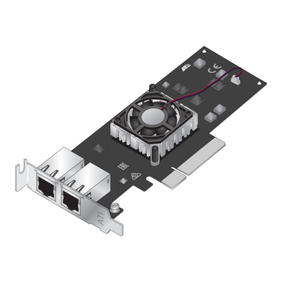
Chapter 1: Introduction ANC10T/2 Network Interface Card Twisted Pair Copper Ports The ANC10T/2 network interface card has two 1/10Gbps copper ports. The card uses Auto-Negotiation to automatically set port speed and supports full-duplex mode only. Each port has two status LEDs. The network interface card has a PCIe x8 motherboard bus connector as shown in Figure 3. -
Page 23: Table 3. Anc10T/2 Link And Activity Leds
ANC10 Network Interface Card Series Installation and User’s Guide The minimum cable requirements are listed here: 1Gbps - Standard TIA/EIA 568-B-compliant Category ❒ 5e twisted pair cabling 10Gbps - Standard TIA/EIA 568-C-compliant Category ❒ 6A twisted pair cabling The port has a maximum operating distance of 100 meters (328 feet). The LEDs for the twisted pair ports are described in Table 3. -
Page 24: Features
Chapter 1: Introduction Features The following features apply to the ANC10 Network Interface Card Series: Encapsulated Task Offload Encapsulation Overhead Energy Efficient Ethernet Flow Control Forward Error Correction Interrupt Moderation (low/medium/high) Jumbo Frames (9174 bytes) ... -
Page 25: Software
ANC10 Network Interface Card Series Installation and User’s Guide VXLAN Encapsulated Task Offload Data Center Bridging PXE Boot (EFI and Legacy) iSCSI Boot (Legacy only) NIC Partitioning (up to 8 partitions per port) RDMA (remote direct memory access) ... - Page 26 Chapter 1: Introduction...
-
Page 27: Chapter 2: Installing The Hardware
Chapter 2 Installing the Hardware This chapter describes how to install the ANC10 Network Interface Card Series in a computer and discusses the following topics: “Reviewing Safety Precautions” on page 28 “Pre-Installation Checklist” on page 30 “Installing the Standard Bracket on the Network Interface Card” on ... -
Page 28: Reviewing Safety Precautions
Chapter 2: Installing the Hardware Reviewing Safety Precautions Important: Safety statements that have the symbol are translated into multiple languages in the Translated Safety Statements document at www.alliedtelesis.com/library. Remarque: Les consignes de sécurité portant le symbole sont traduites dans plusieurs langues dans le document Translated Safety Statements, disponible à... - Page 29 ANC10 Network Interface Card Series Installation and User’s Guide Warning The network interface card is being installed in a system that operates with voltages that can be lethal. Before you remove the cover of your system, you must observe the following precautions to protect yourself and to prevent damage to the system components.
-
Page 30: Pre-Installation Checklist
1. Check that your computer has an appropriate open PCIe slot. 2. Verify that your system is using the latest BIOS. 3. When you download the driver software from the Allied Telesis website, record the path to where the driver file resides on your system. -
Page 31: Installing The Standard Bracket On The Network Interface Card
ANC10 Network Interface Card Series Installation and User’s Guide Installing the Standard Bracket on the Network Interface Card The network interface card is shipped with the low-profile bracket already installed. A standard bracket is included with the network interface card. Depending on your system, you may need to replace the bracket attached to your card. -
Page 32: Figure 6: Installing The Standard Bracket
Chapter 2: Installing the Hardware Figure 6. Installing the Standard Bracket... -
Page 33: Installing The Network Interface Card
ANC10 Network Interface Card Series Installation and User’s Guide Installing the Network Interface Card The following installation instructions apply to most systems. For details about performing the tasks on your particular system, refer to the manuals that were supplied with your system. Note The ANC10 Network Interface Card Series requires a system with an available PCIe x8 slot. - Page 34 Cables to the ANC10T/2 Network Interface Card” on page 36. 9. Power on the system. Download the driver from the Allied Telesis web site. For instructions on how to install the driver on Linux or VMware systems, refer to the README file included with the driver.
-
Page 35: Installing Sfp+ Transceivers In The Anc10Sa/2 Network Interface Card
ANC10 Network Interface Card Series Installation and User’s Guide Installing SFP+ Transceivers in the ANC10Sa/2 Network Interface Card Here are the guidelines to installing and cabling SFP+ transceivers in the ANC10Sa/2 network interface card: SFP+ transceivers can be hot-swapped while the network interface ... -
Page 36: Connecting Twisted-Pair Copper Cables To The Anc10T/2 Network Interface Card
4. Repeat steps 1 through 3 with the second cable and port. Download the driver from the Allied Telesis web site. For instructions on how to install the driver on Linux or VMware systems, refer to the README file included with the driver. For instructions on loading the driver on a Microsoft Windows system, refer to Chapter 3, “Installing the... -
Page 37: Chapter 3: Installing The Windows Driver Software
Chapter 3 Installing the Windows Driver Software This chapter describes how to install driver software for the ANC10 Network Interface Card Series onto your Windows operating system. It contains the following topics: “Overview” on page 38 ❒ “Downloading the Driver Software” on page 39 ❒... -
Page 38: Overview
Chapter 3: Installing the Windows Driver Software Overview After you install the ANC10Sa/2 or ANC10T/2 network interface card in your computer, your next step is to install the driver software onto your Windows operating system. You can install the driver software using the Device Manager or the silent installation method. -
Page 39: Downloading The Driver Software
ANC10 Network Interface Card Series Installation and User’s Guide Downloading the Driver Software The driver software for the network interface card s is available on the Allied Telesis website. The driver is the same for both network interface cards ANC10 Series. To download the software: 1. -
Page 40: Figure 9: Support Window
4. If you have not established a Login ID and Password, click Support. The support window appears. Figure 9. Support Window 5. Click Allied Telesis Support Portal. The Support Portal window appears. Figure 10. Support Portal Window 6. Click Sign Up. -
Page 41: Figure 11: Register For An Account Window
8. Check your email for the access Login ID and password. Allow up to 24 business hours. 9. Go back to the Download Center. 10. Select the driver for the ANC10 Series network interface card and your operating system. 11. Save the zip folder onto your system. - Page 42 Chapter 3: Installing the Windows Driver Software 13. Specify the location of the folder and click Extract. 14. Record the location of the folder.
-
Page 43: Accessing The Windows Device Manager
ANC10 Network Interface Card Series Installation and User’s Guide Accessing the Windows Device Manager When you install or update the driver software for the ANC10 Network Interface Card Series on a Windows system, you must first access the Device Manager. The procedures for accessing the Device Manager are slightly different among Windows operating systems. -
Page 44: Figure 14: Device Manager Window
Chapter 3: Installing the Windows Driver Software The Device Manager window appears. Figure 14. Device Manager Window Option 2 Another option to accessing the Device Manager is: 1. Type Device Manager in the search field at the bottom left corner. The following screen appears. -
Page 45: Installing The Driver Software
ANC10 Network Interface Card Series Installation and User’s Guide Installing the Driver Software Once you physically install the ANC10 Series network card, the system detects the new hardware and creates an entry in the Device Manager when the Windows operating system boots up. Shortly after you log in, you need to install the driver software for your network interface card. -
Page 46: Figure 17: Selecting The Network Adapter In The Device Manager
Note The Device Manager may identify the new network interface card as an Ethernet Controller, Broadcom device, or Allied Telesis device. The shortcut menu appears. See Figure 17 as an example. Figure 17. Selecting the Network Adapter in the Device Manager b. -
Page 47: Figure 18: Update Driver Software Window
See Figure 19 as an example. Figure 19. Browse for Drivers on Your Computer 4. Specify the folder where you stored the driver after downloading it from the Allied Telesis web site. See “Downloading the Driver Software” on page 39 for details. 5. Click Next. -
Page 48: Updating The Driver Software
Chapter 3: Installing the Windows Driver Software Updating the Driver Software Allied Telesis may periodically post updates to the driver software for network interface cards on its web site. To obtain the latest version of the ANC10 Network Interface Card Series driver, see “Downloading the Driver Software”... -
Page 49: Performing The Silent Installation
Note You can apply the silent installation method only to Microsoft certified drivers. The drivers that Allied Telesis provides for the network interface cards are all Microsoft certified. Use a command line utility called Driver Package Installer (DPInst) for the silent installation. -
Page 50: Viewing Supported Dpinst Options
Chapter 3: Installing the Windows Driver Software 7. Change the directory to the folder where the utility and the dpinst driver files reside. 8. Install the driver in the silent mode by entering the following command: > dpinst /S Note Adding the /S switch to the dpinst command suppresses the display of wizard pages, user dialog boxes, and other user intervention requests. -
Page 51: Chapter 4: Modifying Advanced Properties
Chapter 4 Modifying Advanced Properties This chapter includes the following topics: “Overview” on page 53 “Accessing Advanced Properties” on page 54 “Encapsulated Task Offload” on page 56 “Encapsulation Overhead” on page 57 “Energy-Efficient Ethernet” on page 58 ... - Page 52 Chapter 4: Modifying Advanced Properties “RoCE MTU” on page 91 “RSS Base Processor Group” on page 92 “RSS Base Processor Number” on page 93 “RSS Load Balancing Profile” on page 94 “RSS Max Processor Group” on page 96 ...
-
Page 53: Overview
ANC10 Network Interface Card Series Installation and User’s Guide Overview The ANC10 Series of network interface cards allow you to modify advanced properties to meet your requirements. To access the advanced properties, access Device Manager, then go to each advanced property window. -
Page 54: Accessing Advanced Properties
Chapter 4: Modifying Advanced Properties Accessing Advanced Properties To modify advanced properties, first access Device Manager, open the properties of your network interface card, and select a feature. 1. Access the Device Manager. See “Accessing the Windows Device Manager” on page 43. 2. -
Page 55: Figure 21: Device Manager Window - Network Adapters
ANC10 Network Interface Card Series Installation and User’s Guide 3. Double-click AT-ANC10Sa/2 (or AT-ANC10T/2) 10G Dual Port Adapter. Refer to Figure 21. Figure 21. Device Manager Window - Network Adapters The properties window pops up. 4. Click the Advanced tab. The Advanced Properties window opens as shown in Figure 22. -
Page 56: Encapsulated Task Offload
Chapter 4: Modifying Advanced Properties Encapsulated Task Offload The Encapsulated Task Offload property allows the network adapter to perform offload operations such as large send offload (LSO) and virtual machine queue (VMQ) on the inner header for encapsulated packets. Network performance may be degraded by running this cmdlet. To view the Encapsulated Task Offload feature, do the following: 1. -
Page 57: Encapsulation Overhead
ANC10 Network Interface Card Series Installation and User’s Guide Encapsulation Overhead The Encapsulation Overhead property defines the amount of overhead required in Ethernet frames due to virtual network overlay encapsulation such as VXLAN and NVGRE. To view the Encapsulation Overhead feature, do the following: 1. -
Page 58: Energy-Efficient Ethernet
Chapter 4: Modifying Advanced Properties Energy-Efficient Ethernet The Energy-Efficient Ethernet property allows you to optimize the energy usage of the interface over Ethernet. Note This feature is valid only for the copper ports on the ANC10T/2 network interface card. To view the Energy-Efficient Ethernet feature, do the following: 1. - Page 59 ANC10 Network Interface Card Series Installation and User’s Guide 3. Select one of the following options: Disabled — This setting disables Energy-Efficient Ethernet on the ports of the ANC10T/2 network interface card. Enabled — This setting enables Energy-Efficient Ethernet on the ...
-
Page 60: Flow Control
Chapter 4: Modifying Advanced Properties Flow Control The Flow Control property allows you to control the flow between the ANC10 network interface card port and its link partner. You can enable or disable the network interface card port to process received PAUSE frames and transmit PAUSE frames. - Page 61 ANC10 Network Interface Card Series Installation and User’s Guide Rx Enabled — The network interface card processes ingress PAUSE frames, but does not transmit PAUSE frames. Tx Enabled — The network interface card transmits PAUSE frames, but ignores ingress PAUSE frames. 4.
-
Page 62: Forward Error Correction
Chapter 4: Modifying Advanced Properties Forward Error Correction The Forward Error Correction property allows for errors in the received packet to be corrected without the need for a packet re-transmission. To specify or change the Forward Error Correction feature, do the following: 1. - Page 63 ANC10 Network Interface Card Series Installation and User’s Guide 4. Click OK.
-
Page 64: Interrupt Moderation
Chapter 4: Modifying Advanced Properties Interrupt Moderation The Interrupt Moderation property allows you to limit the rate of interrupts to the CPU during packet transmission and packet reception. When this feature is enabled, interrupts are handled as a group so that the CPU utilization decreases;... -
Page 65: Interrupt Moderation Configuration
ANC10 Network Interface Card Series Installation and User’s Guide Interrupt Moderation Configuration The Interrupt Moderation Configuration property sets the level of interrupt moderation. To specify or change the Interrupt Moderation Configuration feature, do the following: 1. Access the Advanced Properties. See “Accessing Advanced Properties”... -
Page 66: Jumbo Packet
Chapter 4: Modifying Advanced Properties Jumbo Packet The Jumbo Packet property enables the network interface card to transmit and receive oversized Ethernet frames that are greater than 1500 bytes, but less than or equal to 9336 bytes in length. To increase the maximum frame size, choose one of the values from the drop-down list. -
Page 67: Large Send Offload V2 (Ipv4)
ANC10 Network Interface Card Series Installation and User’s Guide Large Send Offload v2 (IPv4) Normally, the TCP segmentation is done by the protocol stack. When you enable the Large Send Offload property, the TCP segmentation can be done by the network interface card. The default setting for this property is Enabled. -
Page 68: Large Send Offload V2 (Ipv6)
Chapter 4: Modifying Advanced Properties Large Send Offload v2 (IPv6) The Large Send Offload v2 (IPv6) property allows you to control the load of sending out large packets. When this feature is enabled, the network interface card port segments large packets for IPv6 traffic and reduces the CPU load. - Page 69 ANC10 Network Interface Card Series Installation and User’s Guide 4. Click OK.
-
Page 70: Locally Administered Address
Chapter 4: Modifying Advanced Properties Locally Administered Address The Locally Administered Address property is a user-defined MAC address that is used in place of the MAC address originally assigned to the network interface card. Every network interface card in the network must have its own unique MAC address. - Page 71 ANC10 Network Interface Card Series Installation and User’s Guide Note The appropriate assigned ranges and exceptions for the locally administered address include the following: The range is 00:00:00:00:00:01 to FF:FF:FF:FF:FF:FD. Do not use a multicast address (least significant bit of the high byte = 1).
-
Page 72: Maximum Number Of Msi-X Messages
Chapter 4: Modifying Advanced Properties Maximum Number of MSI-X Messages Message-signaled interrupts provide an in-band method of signaling interrupts to the host processor which can be used as an alternative to traditional out of band methods. To enable or disable the Maximum Number of MSI-X Messages feature, do the following: 1. -
Page 73: Maximum Number Of Rss Processors
ANC10 Network Interface Card Series Installation and User’s Guide Maximum Number of RSS Processors The Maximum Number of RSS Processors property sets the maximum number of processors that will be available for use with Receive Side Scaling. To specify or change the Maximum Number of RSS Processors feature, do the following: 1. -
Page 74: Maximum Number Of Rss Queues
Chapter 4: Modifying Advanced Properties Maximum Number of RSS Queues The Maximum Number of RSS Queues property assigns data to queues associated with physical CPU cores. You can specify the maximum number of RSS queues that the network interface card assigns receiving data to. -
Page 75: Maximum Rss Processor Number
ANC10 Network Interface Card Series Installation and User’s Guide Maximum RSS Processor Number The Maximum RSS Processor Number property sets the highest processor number that will available for use with Receive Side Scaling (RSS). To specify or change the Maximum RSS Processor Number feature, do the following: 1. -
Page 76: Network Direct Functionality
Chapter 4: Modifying Advanced Properties Network Direct Functionality The Network Direct Functionality property enables or disables the Remote Direct Memory Access (RDMA) feature. To enable or disable the Network Direct Functionality feature, do the following: 1. Access the Advanced Properties. See “Accessing Advanced Properties”... -
Page 77: Network Direct Technology
ANC10 Network Interface Card Series Installation and User’s Guide Network Direct Technology The Network Direct Technology property sets the RDMA type that will be used (RDMA over Converged Ethernet or RDMA over Converged Ethernet Version 2). To specify or change the Network Direct Technology feature, do the following: 1. -
Page 78: Nvgre Encapsulated Task Offload
Chapter 4: Modifying Advanced Properties NVGRE Encapsulated Task Offload The NVGRE Encapsulated Task Offload property enables/disables task offloads for NVGRE encapsulated packets. To specify or change the NVGRE Encapsulated Task Offload feature, do the following: 1. Access the Advanced Properties. See “Accessing Advanced Properties”... -
Page 79: Packet Direct
ANC10 Network Interface Card Series Installation and User’s Guide Packet Direct The Packet Direct property enables a low-latency data path between the NIC and packet direct enabled virtual switch. To specify or change the Packet Direct feature, do the following: 1. -
Page 80: Preferred Numa Node
Chapter 4: Modifying Advanced Properties Preferred NUMA Node The Preferred NUMA Node property sets the processor bus number that will be used for the NIC to access host memory. To specify or change the Preferred NUMA Node feature, do the following: 1. -
Page 81: Priority & Vlan
ANC10 Network Interface Card Series Installation and User’s Guide Priority & VLAN The Priority & VLAN property allows you to control sending and receiving tagged frames of QoS and VLAN. When the property is set to Priority & VLAN Enabled, the network interface card sends and receives QoS and VLAN tagged frames;... - Page 82 Chapter 4: Modifying Advanced Properties Priority & VLAN Enabled — Allows for packet prioritization and VLAN tagging. This is the default setting. Packet Enabled — Allows packet prioritization only. VLAN Enabled — Allows VLAN tagging only. 4. Click OK.
-
Page 83: Ptp Hardware Timestamp
ANC10 Network Interface Card Series Installation and User’s Guide PTP Hardware Timestamp The PTP Hardware Timestamp property generates timestamps using the network interface card's own hardware clock. This feature is used in particular by the Precision Time Protocol (PTP), which is a time synchronization protocol. -
Page 84: Quality Of Service
Chapter 4: Modifying Advanced Properties Quality of Service The Quality of Service property enables the processing of QoS-enabled frames. To enable or disable the Quality of Service feature, do the following: 1. Access the Advanced Properties. See “Accessing Advanced Properties” on page 54. 2. -
Page 85: Receive Buffers (0=Auto)
ANC10 Network Interface Card Series Installation and User’s Guide Receive Buffers (0=Auto) The Receive Buffers are data segments that allow the network interface card to allocate receive packets to memory. To specify or change the Receive Buffers feature, do the following: 1. -
Page 86: Receive Side Scaling
Chapter 4: Modifying Advanced Properties Receive Side Scaling The Receive Side Scaling (RSS) property allows the network interface card to efficiently distribute receive processing across multiple CPU’s so as to prevent overloading a single CPU. To make this feature effective, the computer must have multiple CPU’s in a multiprocessor system. -
Page 87: Recv Segment Coalescing (Ipv4)
ANC10 Network Interface Card Series Installation and User’s Guide Recv Segment Coalescing (IPv4) When receiving data, the miniport driver, NDIS, and TCP/IP must all look at each segment's header information separately. When large amounts of data are being received, this creates a large amount of overhead. Receive segment coalescing (RSC) reduces this overhead by coalescing a sequence of received segments and passing them to the host TCP/IP stack in one operation, so that NDIS and TCP/IP need only look at one... - Page 88 Chapter 4: Modifying Advanced Properties 4. Click OK.
-
Page 89: Recv Segment Coalescing (Ipv6)
ANC10 Network Interface Card Series Installation and User’s Guide Recv Segment Coalescing (IPv6) When receiving data, the miniport driver, NDIS, and TCP/IP must all look at each segment's header information separately. When large amounts of data are being received, this creates a large amount of overhead. Receive segment coalescing (RSC) reduces this overhead by coalescing a sequence of received segments and passing them to the host TCP/IP stack in one operation, so that NDIS and TCP/IP need only look at one... - Page 90 Chapter 4: Modifying Advanced Properties 4. Click OK.
-
Page 91: Roce Mtu
ANC10 Network Interface Card Series Installation and User’s Guide RoCE MTU The RDMA over Converged Ethernet (RoCE) Maximum Transmission Unit (MTU) property sets the maximum packet size for RDMA packets. To specify or change the RoCE MTU feature, do the following: 1. -
Page 92: Rss Base Processor Group
Chapter 4: Modifying Advanced Properties RSS Base Processor Group The RSS Base Processor Group property defines the base processor group for the RSS queues on the network adapter. To specify or change the RSS Base Processor Group feature, do the following: 1. -
Page 93: Rss Base Processor Number
ANC10 Network Interface Card Series Installation and User’s Guide RSS Base Processor Number The RSS Base Processor Number property may be set to explicitly define the CPU affinity for the RSS queues of this device. It is the CPU number of the lowest RSS queue for this device. -
Page 94: Rss Load Balancing Profile
Chapter 4: Modifying Advanced Properties RSS Load Balancing Profile The RSS Load Balancing Profile property sets the profile that RSS will use to determine how to scale receive functions across CPUs. To specify or change the RSS Load Balancing Profile feature, do the following: 1. - Page 95 ANC10 Network Interface Card Series Installation and User’s Guide – Closest processor static: No dynamic load balancing, such as distributing but not load balancing at runtime. – Conservative scaling: RSS uses as few processors as possible to sustain the load. This option helps reduce the number of interrupts.
-
Page 96: Rss Max Processor Group
Chapter 4: Modifying Advanced Properties RSS Max Processor Group The RSS Max Processor Group property value defines the maximum number of processor groups for the RSS CPUs in use. To specify or change the RSS Max Processor Group feature, do the following: 1. -
Page 97: Software Timestamp
ANC10 Network Interface Card Series Installation and User’s Guide Software Timestamp The Software Timestamp property allow for the generation of network timestamps to be done at the software level. To specify or change the Software Timestamp feature, do the following: 1. - Page 98 Chapter 4: Modifying Advanced Properties Click OK. ...
-
Page 99: Speed & Duplex
ANC10 Network Interface Card Series Installation and User’s Guide Speed & Duplex The Speed & Duplex property sets the connection speed and mode to that of the network. Note that Full-Duplex mode allows the network interface card to transmit and receive network data simultaneously. To specify or change the Speed &... - Page 100 Chapter 4: Modifying Advanced Properties Auto Negotiation — Use this setting when connecting to a 1 or 10 Gbps link partner that is configured for Auto-Negotiation. ANC10 Network Interface Card Series will attempt to detect the maximum speed supported by the installed SFP module, and will set the port speed to match.
-
Page 101: Sr-Iov
ANC10 Network Interface Card Series Installation and User’s Guide SR-IOV The Single Root I/O Visualization (SR-IOV) property allows guest operating systems in a virtualized environment direct access to the NICs PCIe bus and physical functions as opposed to being virtualized by the hypervisor. -
Page 102: Tcp/Udp Checksum Offload (Ipv4)
Chapter 4: Modifying Advanced Properties TCP/UDP Checksum Offload (IPv4) The TCP/UDP Checksum Offload (IPv4) property enables the network interface card port to compute the checksum of transmitting IPv4 packets and verify the checksum of receiving IPv4 packets, taking load off from the CPU. - Page 103 ANC10 Network Interface Card Series Installation and User’s Guide Rx Enabled — Enables the TCP/UDP Checksum Offload (IPv4) function only for receiving IPv4 packets. Tx Enabled — Enables the TCP/UDP Checksum Offload (IPv4) function only for transmitting IPv4 packets. 4.
-
Page 104: Tcp/Udp Checksum Offload (Ipv6)
Chapter 4: Modifying Advanced Properties TCP/UDP Checksum Offload (IPv6) The TCP/UDP Checksum Offload (IPv6) property enables the network interface card port to compute the checksum of transmitting IPv6 packets and verify the checksum of receiving IPv6 packets, taking load off from the CPU. - Page 105 ANC10 Network Interface Card Series Installation and User’s Guide Rx Enabled — Enables the TCP/UDP Checksum Offload (IPv6) function only for receiving IPv6 packets. Tx Enabled — Enables the TCP/UDP Checksum Offload (IPv6) function only for transmitting IPv6 packets. 4.
-
Page 106: Transmit Buffers (0=Auto)
Chapter 4: Modifying Advanced Properties Transmit Buffers (0=Auto) The Transmit Buffers property value is the number of transmit buffers allowed. Transmit buffers are segments of system memory allocated to processing transmit packets. To specify or change the Transmit Buffers feature, do the following: 1. -
Page 107: Udp Segmentation Offload (Ipv4)
ANC10 Network Interface Card Series Installation and User’s Guide UDP Segmentation Offload (IPv4) The UDP Segmentation Offload (USO) property allows the NIC to perform the segmentation of UDP datagrams that are larger than the maximum transmission unit (MTU) of the network medium. By doing so, Windows reduces CPU utilization associated with per-packet TCP/IP processing. -
Page 108: Udp Segmentation Offload (Ipv6)
Chapter 4: Modifying Advanced Properties UDP Segmentation Offload (IPv6) O) property allows the NIC to perform the segmentation of UDP datagrams that are larger than the maximum transmission unit (MTU) of the network medium. By doing so, Windows reduces CPU utilization associated with per-packet TCP/IP processing. -
Page 109: Vf Spoofing Protection
ANC10 Network Interface Card Series Installation and User’s Guide VF Spoofing Protection The Virtual Function (VF) Spoofing Protection property prevents malicious intent under the guise of legitimate behavior. To specify or change the VF Spoofing Protection feature, do the following: 1. -
Page 110: Virtual Machine Queues
Chapter 4: Modifying Advanced Properties Virtual Machine Queues The Virtual Machine Queues property allows the NIC to cache external network traffic to dedicated storage areas on the NIC to be accessed by individual virtual machines. To enable or disable the Virtual Machine Queues feature, do the following: 1. -
Page 111: Virtual Switch Rss
ANC10 Network Interface Card Series Installation and User’s Guide Virtual Switch RSS The Virtual Switch RSS property enables network traffic processing to be scaled over multiple host CPUs for virtual machines. To specify or change the Virtual Switch RSS feature, do the following: 1. -
Page 112: Vlan Id
Chapter 4: Modifying Advanced Properties VLAN ID The VLAN ID property allows you to specify a VLAN ID on your network to the network interface card port. The network interface card port adds the value of the VLAN ID to a frame in the VLAN tag before transmitting the frame. -
Page 113: Vxlan Encapsulated Task Offload
ANC10 Network Interface Card Series Installation and User’s Guide VXLAN Encapsulated Task Offload The VXLAN Encapsulated Task Offload property allows for the use of Encapsulated Task offload functions in a VXLAN environment To specify or change the VXLAN Encapsulated Task Offload feature, do the following: 1. - Page 114 Chapter 4: Modifying Advanced Properties...
-
Page 115: Chapter 5: Uninstalling The Driver Software
Chapter 5 Uninstalling the Driver Software This chapter describes how to uninstall driver software for the ANC10 Network Interface Card Series onto your Windows operating system. It contains the following topics: “Overview” on page 116 “Uninstalling the Driver Software Using Device Manager” on page 117 ... -
Page 116: Overview
Chapter 5: Uninstalling the Driver Software Overview When you no longer use the ANC10Sa/2 or ANC10T/2 for your computer, you can uninstall the driver software from your operating system. As you can install driver software for the network interface card using Device Manager or the silent installation method, you can also uninstall driver software in two ways: “Uninstalling the Driver Software Using Device Manager”... -
Page 117: Uninstalling The Driver Software Using Device Manager
See “Accessing the Windows Device Manager” on page 43. 3. In the Device Manager window, expand the Network Adapters folder. 4. Right-click the Allied Telesis AT-ANC10Sa/2 (or AT-ANC10T/2) 10G Dual Port Adapter. The shortcut menu appears as shown in Figure 68. -
Page 118: Figure 69: Deleting The Driver Software
Chapter 5: Uninstalling the Driver Software Figure 69. Deleting the Driver Software 6. Check the check box if you want to remove the driver software for your network interface card. 7. Click Uninstall to complete the uninstall. -
Page 119: Uninstalling The Driver Software Silently
ANC10 Network Interface Card Series Installation and User’s Guide Uninstalling the Driver Software Silently You can apply the silent installation method to uninstall the driver. To uninstall the driver without user-intervention, perform the following steps: 1. Open a command prompt window with administrator privileges. 2. - Page 120 Chapter 5: Uninstalling the Driver Software...
-
Page 121: Appendix A: Technical Specifications
Appendix A Technical Specifications This appendix contains the following sections: “Physical Specifications” on page 121 “Environmental Specifications” on page 122 “Power Specifications” on page 122 “Performance Specification” on page 122 “Compliance Requirements” on page 123 Physical Specifications Table 4 contains the dimensions and weight of the network interface card. -
Page 122: Environmental Specifications
Appendix A: Technical Specifications Environmental Specifications Table 5 contains the environmental specifications of the network interface card. Table 5. Environmental Specifications Environmental Specification Value Operating Temperature 0° C to 35° C (32° F to 95° F) Storage Temperature -30° C to 70° C (-22° F to 158° F) Operating Humidity 5% to 95% non-condensing Storage Humidity... -
Page 123: Compliance Requirements
ANC10 Network Interface Card Series Installation and User’s Guide Compliance Requirements Table 7 contains the specifications of the compliance requirements. Table 7. Compliance Requirements Item Specification Safety UL62368-1 ( CSA C22.2 No. 62368-1 EN62368-1 (TUV) Emissions (EMI) FCC Part 15 EN55032 Class B VCCI, Class B ICES-003... - Page 124 Appendix A: Technical Specifications...
Need help?
Do you have a question about the ANC10 Series and is the answer not in the manual?
Questions and answers