
Related Manuals for Allied Telesis Rapier i AT-RP16Fi/SC


Summary of Contents for Allied Telesis Rapier i AT-RP16Fi/SC
- Page 1 Network Service Module Installation and Safety Guide AT-AR040 AT-AR041 AT-AR042 AT-AR048...
- Page 2 Network Service Module Installation and Safety Guide AT-AR040 AT-AR041 AT-AR042 AT-AR048 Download the complete document set from www.alliedtelesis.com/support/software...
- Page 3 Network Service Module Installation and Safety Guide Document Number 613-000610 Rev B. © 2007 Allied Telesis, Inc. All rights reserved. No part of this publication may be reproduced without prior written permission from Allied Telesis, Inc. Allied Telesis, Inc. reserves the right to change specifications and other information in this document without prior written notice.
-
Page 4: Table Of Contents
Installation and Safety Guide Contents About this Guide ... 4 Compatible Switches and Routers ... 4 Package Contents ... 5 Hot Swapping ... 6 Installing a Network Service Module ... 7 LEDs and What They Mean ... 10 Obtaining Documentation and Resources ... 12 613-000610 Rev B... -
Page 5: About This Guide
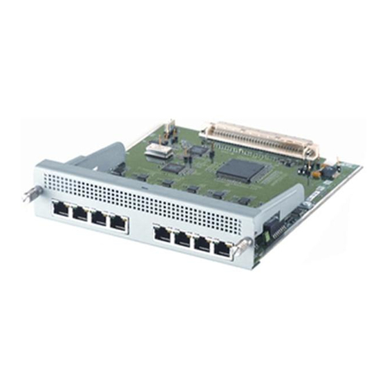
About this Guide This Installation and Safety Guide describes how to install the following Network Service Modules (NSMs): AT-AR040, four Port Interface Card (PIC) expansion bays ■ AT-AR041, eight ISDN Basic Rate S/T interfaces ■ AT-AR042, four ISDN Basic Rate S/T interfaces ■... -
Page 6: Package Contents
1 EA Made in Singapore Package Contents The following items are included with each Network Service Module (NSM). Contact your authorised Allied Telesis distributor or reseller if any items are damaged or missing. one NSM ■ this Installation and Safety Guide ■... -
Page 7: Hot Swapping
Hot Swapping There are two methods for installing and removing NSMs: the standard installation method and the hot swap installation method. The software release running on your switch or router determines which of these two methods should be used. If your switch or router is running Software Version 2.2.3 or earlier, follow the standard method. -
Page 8: Installing A Network Service Module
Installation and Safety Guide Installing a Network Service Module Warning Failure to follow this procedure when hot swapping an NSM will cause the switch or router to halt, and may damage it and any files stored in flash memory. Read the safety information. See the Installation and Safety Guide or Safety and Statutory Information Booklet for your switch or router. - Page 9 Warning Do not attempt to install an NSM without observing correct antistatic procedures. Failure to do so may damage the switch, router, or NSM. If you are unsure what the correct procedures are, contact your authorised Allied Telesis distributor or reseller. 613-000610 Rev B Network Service Module...
- Page 10 Installation and Safety Guide Slide the NSM into place. Slide the NSM into the NSM bay, making sure the ends of the captive screws are aligned with the screw holes on the switch or router. If the NSM has extractor levers, they should be in the closed position. Secure the NSM.
-
Page 11: Leds And What They Mean
LEDs and What They Mean The following LEDs report operations and faults on NSMs: “AT-AR041 and AT-AR042 LEDs” on page 10 ■ “AT-AR048 LEDs” on page 11 ■ “Switch and Router LEDs” on page 11 ■ The AT-AR040 NSM unit does not have independent LEDs. See LEDs”... - Page 12 Installation and Safety Guide AT -AR048 LEDs The following table describes LEDs on the AT-AR048 NSM. State Active Green Loop Green Amber Amber Amber FERF Amber Switch and Router LEDs The following table describes LEDs on switches and routers that support NSMs. In Use (rear panel) Green Swap (rear panel) Function...
-
Page 13: Obtaining Documentation And Resources
You can download it from www.adobe.com. Other resources How-To Notes describe a range of standard Allied Telesis solutions, and include technical tips and guides to configuring specific hardware and software features. You can download the latest How-To Notes from www.alliedtelesis.com/resources/literature/howto.aspx.
Need help?
Do you have a question about the Rapier i AT-RP16Fi/SC and is the answer not in the manual?
Questions and answers