
Related Manuals for Meinberg IMS - LANTIME M3000S


Summary of Contents for Meinberg IMS - LANTIME M3000S
- Page 1 MANUAL IMS - LANTIME M3000S Modular Sync. System and NTP Server August 11, 2023 Meinberg Funkuhren GmbH & Co. KG...
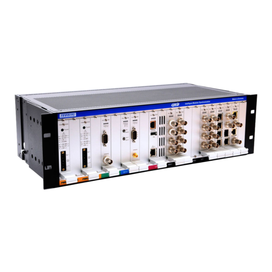
- Page 3 Front view (Frontansicht) IMS - LANTIME M3000S 10MHz Clock Signal...
-
Page 4: Table Of Contents
Table of Contents 1 Imprint 2 Copyright and Liability Exclusion 3 The System LANTIME IMS M3000S IMS - Systems ..........Target Audience . - Page 5 Meinberg Newsletter ........
-
Page 6: Imprint
1 Imprint 1 Imprint Meinberg Funkuhren GmbH & Co. KG Lange Wand 9, 31812 Bad Pyrmont, Germany Phone: + 49 (0) 52 81 / 93 09 - 0 Fax: + 49 (0) 52 81 / 93 09 - 230 Website: https://www.meinbergglobal.com... -
Page 7: Copyright And Liability Exclusion
Meinberg reserves the right to make changes of any type to this document at any time as is necessary for the purpose of improving its products and services and ensuring compliance with applicable standards, laws &... -
Page 8: The System Lantime Ims M3000S
3.3 Return of Equipment All parts and components of your Meinberg system may only be repaired by Meinberg qualified personnel. In the event of a malfunction, the customer must contact our support service and never attempt to repair the device himself. -
Page 9: Lantime Ims M3000S System Description
SNMP traps or automatically generated emails. It is also possible to have all alerts displayed on a large VP100/20/NET display. To provide redundancy against hardware failure, multiple LANTIME NTP servers can be installed in the same network. Date: August 11, 2023 IMS - LANTIME M3000S... -
Page 10: Ims System Variants
Railmount Chassis The base chassis contains a power supply, a reference clock and a LANTIME CPU. M500: two slots for expansion cards one configurable expansion slot (CES) with two optional output signals IMS - LANTIME M3000S Date: August 11, 2023... -
Page 11: Hardware Specifications
The available configurations can be optimally adapted for specific application areas and industries. ———————- * The dimensions in parentheses take into account the connections and module handles. ** With a redundant receiver configuration, only 3 IO slots are available in an M1000 system. Date: August 11, 2023 IMS - LANTIME M3000S... -
Page 12: Environmental Requirements
1U passive cooling enclosure that can be installed under the IMS system in the server rack. The RCU module (Rack Cooling Unit) provides an optimal airflow for the dissipation of the warm air (see also chapter RCU - Rack Cooling Unit). IMS - LANTIME M3000S Date: August 11, 2023... -
Page 13: Ce Marking
UK statutory instruments applicable and effective as at the time of manufacture of the product. These statutory instruments are listed in the UK Declaration of Conformity, appended to this manual as Chapter 15. Date: August 11, 2023 IMS - LANTIME M3000S... -
Page 14: Important Safety Information
ATTENTION! This signal word refers to a procedure or other action that may result in product damage or the loss of important data if not observed or if improperly performed. IMS - LANTIME M3000S Date: August 11, 2023... -
Page 15: Used Symbols
Dieses Produkt fällt unter die B2B Kategorie. Zur Entsorgung muss es an den Hersteller übergeben werden. This product is handled as a B2B-category product. To ensure that the product is disposed of in a WEEE-compliant fashion, it must be returned to the manufacturer. Date: August 11, 2023 IMS - LANTIME M3000S... -
Page 16: Product Documentation
5 Important Safety Information 5.3 Product Documentation Detailed product documentation is provided on a USB flash drive delivered with the Meinberg system. The manuals can also be downloaded from the Meinberg website at https://www.meinbergglobal.com, where you can enter your system name into the search box at the top of the page to find the relevant manual. Alternatively, contact Meinberg Support for further assistance. -
Page 17: Safety During Installation
For safety reasons, the device with the highest mass should be installed at the lowest position in the rack. Further devices should be installed from the bottom, working your way up. The device must be protected against mechanical & physical stresses such as vibration or shock. Date: August 11, 2023 IMS - LANTIME M3000S... - Page 18 = 90 - 250 V Faulty shielding or cabling and improperly connected plugs are a health & safety risk (risk of injury or death due to electrical shock) and may damage or even destroy your Meinberg device or other equipment.
- Page 19 Date: August 11, 2023 IMS - LANTIME M3000S...
-
Page 20: Connection Of Protective Earth Conductor/Grounding
A grounding cable is not included in the contents of delivery. Note: Please use a grounding cable with cross-section 1.5 mm , as well as a suitable grounding clamp/lug. Always ensure that the connection is properly crimped! IMS - LANTIME M3000S Date: August 11, 2023... -
Page 21: Safety During Operation
UPS power cable from the mains socket. In this case, you will need to shut down your UPS in accordance with the user documentation of your UPS system. Date: August 11, 2023 IMS - LANTIME M3000S... -
Page 22: Safety During Maintenance
(approx. 60 N) presents a risk of injury to the hands. Information on which components are approved for installation can be obtained from Meinberg Technical Support. The device must not be opened. Repairs to the device may only be performed by the manufacturer or authorized personnel. -
Page 23: Handling Of Batteries
The battery is used to power components such as the RAM and the reserve real-time backup clock for the reference clock. If the battery voltage drops below 3 V DC, Meinberg recommends having the battery replaced. If the battery voltage drops below the specified minimum, the following behavior may be... -
Page 24: Safety Information For Sfp Modules
fiber optic or electrical connection. The safety information below must be read and heeded before installing an SFP module in a Meinberg device, before setting up a Meinberg device equipped with SFP modules for use, or before performing maintenance on such a Meinberg device. -
Page 25: Cleaning And Care
ESD-proof bags that are crumpled or have holes cannot provide effective protection against electrostatic discharges. ESD-proof bags must have a sufficient electrical resistance and must not be made of conductive metals if the device has a lithium battery fitted on it. Date: August 11, 2023 IMS - LANTIME M3000S... -
Page 26: Return Of Electrical And Electronic Equipment
When disposing of your old equipment, please use the national return or collection systems available to you. Alternatively, you may contact Meinberg, who will provide further assistance. The return of electronic waste may not be accepted if the device is soiled or contaminated in such a way that it potentially presents a risk to human health or safety. -
Page 27: Before You Start
- e.g. PTP status Parent Datasets . Example: Menü PTP (IEEE1588) Settings Operation Mode Multicast Master Terminal # Output via a terminal window is displayed # in a grey box with monospace font. Date: August 11, 2023 IMS - LANTIME M3000S... -
Page 28: Abbreviation List
Intelligent Electronic Devices RS232/485 Serial port levels IEEE Institute of Electric and Redundant Switch Control unit Electronic Engineers Receiving Data IEEE 1588 Protocol for high-precision Single Board Computer synchronization in nanosecond Signal Distribution Unit IMS - LANTIME M3000S Date: August 11, 2023... - Page 29 Standard for computer data logging VLAN Virtual Local Area Network TACACS Terminal Access Controller WWVB Time signal radio station Access Control System Fort Collins, Colorado (USA) Time Code Generator Time Code Receiver for IRIG A/B, Date: August 11, 2023 IMS - LANTIME M3000S...
-
Page 30: Required Tools
PH1 x 80 PH1 x 80 Replacing TORX T8 TORX T10 Modules Figure: Required tools from left to right - INBUS 2,5mm, Phillips PH1 x 80, Flat head Screwdriver, TORX T20, TORX T8 IMS - LANTIME M3000S Date: August 11, 2023... -
Page 31: Preparing Installation
6.4 Preparing Installation Meinberg IMS LANTIME systems are designed for installation in 19-inch racks or 35mm rail mount. Rack systems come with all necessary accessories (mounting brackets, screws, adapters for power supply ...). For installations in regions outside of Germany that have other standards for e.g. power supply connections, please specify exactly which adapters or cables you need to put the device into operation when ordering. -
Page 32: Unboxing The Device
Antenna Option: second antenna Antenna cable Option: cable for surge voltage protector Option: surge voltage protector with bracket Brackets for pole or wall mounting (GPS Antenna) Pole for antenna mounting (GPS Antenna) IMS - LANTIME M3000S Date: August 11, 2023... - Page 33 Please read the safety instructions and the manual carefully to familiarize yourself with the safe and proper handling of electronic devices. The product documentation can be found on the USB Flash Memory. Date: August 11, 2023 IMS - LANTIME M3000S...
-
Page 34: Disposal Of Packaging Materials
The packaging materials we use are fully recyclable: Material Use for Disposal ———————————————————————————————————————— Polystyrol packaging frame/filling material Recycling Depot (polystyrene peanuts, bubble wrap) PE-LD accessories packaging Recycling Depot Polyethylene low density Cardboard shipping packaging, Paper recycling accessories packaging ———————————————————————————————————————— IMS - LANTIME M3000S Date: August 11, 2023... -
Page 35: System Installation
Make sure that the voltage is disconnected from the power source during installation. Figure: M3000S rack mount. The screws for rack mounting are not included in the delivery. Date: August 11, 2023 IMS - LANTIME M3000S... -
Page 36: Antenna Connection
A detailed description of the reception modes of our reference clocks and instructions for antenna installa- tion can be found in our LTOS firmware manual: http://www.mbg.link/doce-fw-ltos in chapter "Antenna and Receiver Information". The following table shows the available receiver types from Meinberg Type Receiver Systems Antenna / signal reference ——————————————————————————————————————————————... -
Page 37: Mounting The Antenna
• clear view between 55th north and 55th south parallels (satellite orbits). Information: Problems may arise if all of these views are obstructed, as four satellites must be located to calculate a new position. Date: August 11, 2023 IMS - LANTIME M3000S... - Page 38 Case Example 4: If the cable leading from the point of entry into the building to the Meinberg system is laid together with other cables (for example in a cable duct alongside high-voltage cables), transient voltages may "leak" into the antenna cable, causing damage to your system.
- Page 39 Type-N (Male) If installed in a waterproof housing, the MBG S- Type-N (Female) PRO can be installed outdoors. However, Meinberg recommends installing the surge protector indoors—as closely to the entrance point of the antenna cable as possible—in order to minimize the risk of surge dam- age (such as that caused by lightning strike).
- Page 40 The next step is to connect the supplied coaxial cable from the surge protector to the receiver. Type-N (Female) Type-N (Male) Receiver Optional Antenna Splitter SMA (Male) SMA (Female) BNC (Male) BNC (Female) Type-N (Male) Type-N (Female) IMS - LANTIME M3000S Date: August 11, 2023...
- Page 41 The splitter may be installed at any location between the surge protector and the receivers. Information: Please note for installation purposes that GNSS L1 components cannot be directly connected to or used with a Meinberg GPS antenna distributor. Antenna Receiver Antenna Splitter...
- Page 42 The line of sight between the antenna and satellites should not be obstructed in any way. The antenna must also not be installed under power lines or other electrical lighting or power circuits. IMS - LANTIME M3000S Date: August 11, 2023...
- Page 43 Problems may arise if all of these views are obstructed, as four satellites must be located to calculate a new position. Important Information Regarding Surge Protection Information about Meinberg surge protection can be found in the chapter ?? . Mounting the Antenna Clear view of the sky!
- Page 44 Type-N (Male) If installed in a waterproof housing, the MBG S- PRO can be installed outdoors. However, Meinberg Type-N (Female) recommends installing the surge protector indoors—as closely to the entrance point of the antenna cable as possible—in order to minimize the risk of surge dam-...
- Page 45 The splitter may be installed at any location between the surge protector and the receivers. Information: It is not possible to directly connect a Meinberg GPS antenna/converter unit to an L1 antenna splitter. Antenna Receiver...
- Page 46 7.1.1.4 Technical Specifications: RV-76G GPS/GLONASS Antenna for Mobile Applications Installation of the Antenna Further Information on the Product Detailed specifications are provided in the manufacturer’s data sheet. Source: Datasheet RV-76G_Catalog_V1.0_20130502 (Sanav) https://www.meinbergglobal.com/download/docs/other/rv-76g_en.pdf Download: IMS - LANTIME M3000S Date: August 11, 2023...
- Page 47 DCF77 Long Wave DCF77 Antenna Location: Milan Illustration: Installation of a Meinberg AW02 antenna directed towards the DCF77 transmitter tower in Main- flingen (Frankfurt am Main). For optimum operation, the following should be noted when installing a DCF77 antenna: • The antenna should be mounted horizontally.
- Page 48 Length of antenna facing conditions specified above directly onto a wall using the transmission tower the included mounting kit. Connect the antenna cable to the Type-N connector of the antenna. AW02 Type-N (Female) Type-N (Male) IMS - LANTIME M3000S Date: August 11, 2023...
- Page 49 Ensure that the maximum cable length is not exceeded when laying the antenna cable between the antenna and receiver. Meinberg generally recommends the use of RG58 cable not exceeding 300m; the attenuation data for this cable is provided in Chapter ??, "??".
- Page 50 The AW02 antenna itself provides no visual indication of the reception quality of the DCF77 signal while aligning it. Meinberg therefore recommends that the alignment and signal reception testing be done with the assistance of a second person. An effective method for aligning and testing a long-wave antenna is to have person 1 (who is aligning the antenna) actively communicate with person 2 (who monitors the receiver).
- Page 51 Distance AC = 410 m (RG58) - Max. Total Length Exceeded (Use of Active Signal Distributor Recommended) If the cable length exceeds 300 m, we recommend installing our Meinberg DCF77 AV4 signal distributor be- tween the antenna and the receiver. This not only serves as a signal splitter to allow multiple receivers to be connected to a single antenna, but also (optionally) amplifies the signal.
-
Page 52: Connecting The System
Figure: Connection scheme LANTIME M3000 with power supply, network connector, serial connection and antenna link The following section describes how you can initially put a LANTIME system into operation via LED dis- play, with help of the Web Interface or via serial connection. IMS - LANTIME M3000S Date: August 11, 2023... -
Page 53: Initial Network Configuration
Default user: root Default password: timeserver (press RETURN again if necessary) Change with the console to the directory /wizard/. The LANTIME Basic Configuration Wizard can now be started with the "startwizard" command. Date: August 11, 2023 IMS - LANTIME M3000S... - Page 54 7 System Installation After successfully starting the Wizard, the following welcome screen will be displayed: By entering "y" you start the configuration - all further settings can now be made: Confirm your settings then. IMS - LANTIME M3000S Date: August 11, 2023...
-
Page 55: System Operation - Configuration And Monitoring
Note: Please change these credentials during the first web session on your LANTIME. For detailed documentation about management and monitoring please refer to the latest LTOS firmware manual http://www.mbg.link/doce-fw-ltos or in the menu "Documentation Available Documents" in the web interface. Date: August 11, 2023 IMS - LANTIME M3000S... -
Page 56: Maintenance, Servicing And Repairing
firmware versions and delete versions that are no longer needed. Existing configu- rations can be stored here to save them as backup. Furthermore, configurations from other LANTIMEs can be transferred to the system here. IMS - LANTIME M3000S Date: August 11, 2023... -
Page 57: Troubleshooting And Alarming
Please enter the serial number of your device again and, if already available, a support ticket number. Otherwise there are a lot of tools available for self-help. Please also read the chapter Support Informa- tion. Date: August 11, 2023 IMS - LANTIME M3000S... -
Page 58: System Error Messages
UTC time is displayed, for the notifications the date and UTC time of the last occurrence of the triggered event is displayed. In addition, the event level is also displayed for the notifications (Info, Action, Warning, Error, Critical). IMS - LANTIME M3000S Date: August 11, 2023... -
Page 59: Support Information
11 Support Information In this chapter you will learn about different levels of support at the Meinberg Company. In general, the Basic Customer Support level is included in the price you pay for your Meinberg product and demands no additional costs. -
Page 60: Basic Customer Support
11.2 Support Ticket System Meinberg assists you quickly and directly on questions regarding the initial setup of your devices, troubleshoot- ing or if you want to update the hard- or software. We offer free support for the whole lifetime of your Meinberg product. -
Page 61: How To Download A Diagnostic File
• You can find the Diagnostic File by opening the LANTIME folder and continue on to the Diag folder. USB Memory Stick USB Stick Menu Main Menu (OK to confirm) (OK to confirm) Write Diagnostic Use Up / Down File to USB Stick arrow buttons Date: August 11, 2023 IMS - LANTIME M3000S... -
Page 62: Self-Help Online Tools
11 Support Information 11.4 Self-Help Online Tools Here is the list of some informative websites where you can query different information about the Meinberg Systems. Meinberg Homepage - general: https://www.meinbergglobal.com/ NTP Download - at Meinberg: https://www.meinbergglobal.com/english/sw/ NTP Client Download for Windows (NTP-time-server-monitor): https://www.meinbergglobal.com/english/sw/ntp-server-monitor.htm... -
Page 63: The Meinberg Academy Introduction And Offerings
11.6 The Meinberg Academy introduction and offerings Meinberg Sync Academy (MSA) is an institution within the Meinberg Company which takes care for education and expert knowledge dissemination in the field of time and frequency synchronization. The academy offers tutorials and courses on the latest synchronization technologies such as NTP, IEEE 1588-PTP, synchronization networks for different industries: telecom, power, broadcasting, professional audio/video, finance, IT and . -
Page 64: Attachment: Technical Information
Cold air flows in from the back and is discharged as warm air in front of the rack. Front to back. Cold air flows in from the front and is discharged as warm air behind the rack. IMS - LANTIME M3000S Date: August 11, 2023... -
Page 65: Available Modules And Connectors
120 Ohm (Clock) shielded data line E1/T1 unbalanced 75 Ohm (Bits) shielded data line 10 MHz sine shielded data line REL1000 DFK-3 Error Relay VSG181 Blackburst, DARS, LTC, Word Clk shielded data line Date: August 11, 2023 IMS - LANTIME M3000S... - Page 66 BNC / FST 10 MHz, PPS, IRIG, PPOs shielded data line Video Sync, LTC, Word Clk shielded data line and PPS Input Input/Output Modules: PIO180 PPS, 10 MHz shielded data line IMS - LANTIME M3000S Date: August 11, 2023...
-
Page 67: Terminal (Console)
• backing up the LANTIME configuration • transferring configurations between individual LANTIMES • copying log files • installing firmware updates • uploading and downloading secure certificates (SSL, SSH) and passwords Date: August 11, 2023 IMS - LANTIME M3000S... -
Page 68: Replacement Or Installation Of A Hot-Pluggable Ims Module
Make sure that the module is securely locked into the connector block before you fasten the two screws. Now you can put the installed module into operation. Attachment points of an 1U IMS system IMS - LANTIME M3000S Date: August 11, 2023... -
Page 69: Important Information Regarding Hot-Pluggable Ims Modules
Information: The NTP service and access to the web interface will be unavailable while the CPU is not installed. Management and monitoring functions will also be disabled. Date: August 11, 2023 IMS - LANTIME M3000S... -
Page 70: Ims Module Options
12.6 IMS Module Options 12.6.1 IMS LANTIME IMS M3000S Slot Usage The LANTIME IMS M3000S system supports redundancy and thus allows the use of two Meinberg receivers and up to four power supplies. The following modules can be used in the designated slots: All output modules (BPE, CPE, LIU, LNO, SCG, VSG ...) - Page 71 When more than five HPS modules are installed, the use of an ACM is required. Please note: It is not possible to install an Active Cooling Module (ACM) in an M3000S chassis. Date: August 11, 2023 IMS - LANTIME M3000S...
-
Page 72: Power Supply 100-240 V Ac / 100-200 V Dc
• All connectors must provide protection against contact with live parts in the form of a suitable plug body! • Always ensure that wiring is safe! • The device must be grounded by means of a connection with a correctly installed protective earth conductor (PE). IMS - LANTIME M3000S Date: August 11, 2023... -
Page 73: Power Supply 20-60 V Dc
= 2.1 A Nominal voltage range: 24-48 V Maximum voltage range: 20-60 V Nominal current: 2.1 A Output Parameter ——————————————————————————– Maximum power: 50 W Maximum thermal energy: 180.00 kJ/h (170.61 BTU/h) therm Date: August 11, 2023 IMS - LANTIME M3000S... -
Page 74: Power Supply 10-36 V Dc
——————————————————————————– = 2.5 A Nominal voltage: 24 V Maximum voltage range: 10-36 V Nominal current: 2.5 A Output Parameter ——————————————————————————– Maximum power: 50 W Maximum thermal energy: 180.00 kJ/h (170.61 BTU/h) therm IMS - LANTIME M3000S Date: August 11, 2023... -
Page 75: Ims Receiver Modules
In addition to the redundant receiver configurations with two identical receivers for M1000, M2000, M3000, and M4000 models, it is also possible to configure these housing types with two different receiver systems. Date: August 11, 2023 IMS - LANTIME M3000S... - Page 76 Pin 5: GND Attention: Use this plug only to connect a MEIN- BERG IMS-XHE Rubidium expansion chassis. The XHE-SPI connector is only available for Meinberg GNSS receivers (GPS, GNS, GNS-UC, GNM). 12.6.5.1 GPS Clock IMS - LANTIME M3000S Date: August 11, 2023...
- Page 77 Signal - MRS mode (PPS, IRIG ...) red/yellow (flashing): holdover mode (MRS mode) Fail: red: time has not synchronized Date: August 11, 2023 IMS - LANTIME M3000S...
- Page 78 Signal - MRS mode (PPS, IRIG ...) red/yellow (flashing): holdover mode (MRS mode) Fail red: time has not synchronized IMS - LANTIME M3000S Date: August 11, 2023...
- Page 79 Signal - MRS mode (PPS, IRIG ...) red/yellow (flashing): holdover mode (MRS mode) Fail red: time has not synchronized Date: August 11, 2023 IMS - LANTIME M3000S...
- Page 80 RAM. Life time of lithium battery: min. 10 years Figure right: GNM Multiband receiver and GNM with XHE-SPI connector (optional) IMS - LANTIME M3000S Date: August 11, 2023...
- Page 81 Signal - MRS mode (PPS, IRIG ...) red/yellow (flashing): holdover mode (MRS mode) Fail red: time has not synchronized Date: August 11, 2023 IMS - LANTIME M3000S...
- Page 82 Ant: Red: Antenna faulty or not connected Red/yellow (flashing): Holdover mode (MRS mode) Yellow: The clock is synchronizing to a source other than DCF77 Fail: Red: Time is not synchronized IMS - LANTIME M3000S Date: August 11, 2023...
- Page 83 (flashing): Jitter too large Fail red: the internal timing of the TCR180 is in holdover mode off: the internal timing of the TCR180 is synchronized to the received time code (Lock) Date: August 11, 2023 IMS - LANTIME M3000S...
- Page 84 IRIG-B123 / B122 / / B126 / B127 / B002 / B003 / B006 / B007 IRIG-G142 / G146 / G002 / G006 AFNOR NFS 87-500 C37.118 IEEE1344 Accuracy of Time Base Required Accuracy of Time Code Source: max 100 sec Jitter / offset 1E-5 IMS - LANTIME M3000S Date: August 11, 2023...
- Page 85 7E2, 8N1, 8N2, 8E1, 7N2, 7E1, 801 Mode of operation: string per second string per minute string on request Time telegram: Meinberg Standard, Uni Erlangen, SAT, Meinberg Capture, ION, Computime, SPA, RACAL Capture Inputs Triggered by falling TTL slope Pulse repetition time: 1.5 msec min.
- Page 86 1.5 Vrms output impedance 200 Pulse Outputs Pulse per second (PPS): TTL- and RS-232 level positive pulse, pulse duration 200 msec Pulse per minute (PPM): TTL level positive pulse, pulse duration 200 msec IMS - LANTIME M3000S Date: August 11, 2023...
-
Page 87: Rsc Switch Card
When removing the RSC module or (re)installing one, you will see a number of DIP switches present on the card. Meinberg expressly advises against modifying the positions of these switches. They cannot be used to influence the function or reference clock switching behavior of your IMS system in any meaningful way. - Page 88 SCU INFO -> MANUAL: disabl <- Selected Clk:2 SCU Outputs: * enabled * disabled MANUAL: Enable | Disable Switches between Automatic and Manual Mode Selected Clk: Used to select the active reference clock IMS - LANTIME M3000S Date: August 11, 2023...
-
Page 89: Spt - Single Pass Through
Status: blue: during the initialization phase. green: after initialization of the receiver. Current Consumption: 40 mA Date: August 11, 2023 IMS - LANTIME M3000S... -
Page 90: Lan-Cpu
RJ45 connector console: 38400 / 8N1, connection via CAB-CONSOLE cable USB Port: install firmware upgrades backup and restore configuration files copy security keys lock / unlock front keys Operating System: GNU/Linux 4.x IMS - LANTIME M3000S Date: August 11, 2023... - Page 91 RADIUS, TACACS, FTP, SSH (incl. SFTP, SCP) - SSH v1.3 / SSH v1.5 / SSH v2 (OpenSSH), SNMPv1 (RFC 1157) / SNMPv2c (RFC 1901-1908) / SNMP v3 (RFC 3411-3418), Telnet (RFC 854-RFC 861) Date: August 11, 2023 IMS - LANTIME M3000S...
-
Page 92: Mri - Standard Reference Input Signals
10 MHz input, sine (1.5 V - 5 V or TTL, female BNC connector PPS input, TTL, pulse length 5 s, active high, female BNC connector Figure right: MRI - standard input signals via BNC female connectors IMS - LANTIME M3000S Date: August 11, 2023... - Page 93 LED B: green, if 10 MHz or PPS or both signals are available at the same time Power Requirements: 5 V +-5%, 50 mA Date: August 11, 2023 IMS - LANTIME M3000S...
- Page 94 1. Open the "Clock" menu "Status & Configuration" 2. Select the respective clock module of the corresponding MRI module 3. Click on the tab "MRS settings". 4. Configure the reference signals shown in the priority list. IMS - LANTIME M3000S Date: August 11, 2023...
- Page 95 Configure a required input code and if necessary an offset to UTC. These are to be configured in the "Status & Configuration" submenu in the " IRIG Settings" tab. Menü: Configuration of IRIG-Timecodes Date: August 11, 2023 IMS - LANTIME M3000S...
-
Page 96: Esi - Telecom Synchronisation References
flashing yellow, if only PPS off, if no signal LED B green, if Clock and Framed available flashing green, if only Clock available flashing yellow, if only Framed available off, if no signal IMS - LANTIME M3000S Date: August 11, 2023... - Page 97 An ESI card is, as the MRI card, dedicated to one specific clock module (depending on the slot it is installed in) and can be installed in both ESI as well as MRI slots. Configurable Inputs Input 1: The input 1 is dedicated to 1PPS (Pulse Per Second) synchronization. Date: August 11, 2023 IMS - LANTIME M3000S...
- Page 98 The maximum slip number can be selected in range between 0.5 – 3 cycles, with 1.5 as a default value. Input 3: accepts as input signal configurable frequencies from 1 kHz to 20 MHz. 2048 kHz is set as default value. IMS - LANTIME M3000S Date: August 11, 2023...
- Page 99 TNC will be allowed for synchronization, whereas signal coming from Synchronous Equipment Timing Source (SETS) will not be accepted. Sa Bits With Sa Bits you can select one of the Sa4 to Sa8 bits which is allocated for SSM quality messages. Date: August 11, 2023 IMS - LANTIME M3000S...
-
Page 100: Vsi - Video Synchronization Input Card
Signal level: Frequency range: 1 kHz - 10 MHz PPS Input Input signal: PPS (pulse per second) Signal level: Pulse lenght: 5 s, aktiv high Power Requirements: 5 V, +-5%, 300 mA IMS - LANTIME M3000S Date: August 11, 2023... - Page 101 Reference signal not available / VSI180 is not synchronous Normal Operation: LED St / In green expiration LEDs: ALL LEDs 0,5 sec. red 0,5 sec. yellow 0,5 sec. green 0,5 sec. off Date: August 11, 2023 IMS - LANTIME M3000S...
- Page 102 Input Configuration VSI-Module" Video Sync Interface: configurable Inputs Input 1: Video Sync In Format: PAL 625i Epoch: Signal Source: Single-ended signal input Time Code Modes: VITC Time Code Line: 6 - 22 IMS - LANTIME M3000S Date: August 11, 2023...
- Page 103 Input 2: LTC In Type: LTC 25 FPS (Frames per Second) Input 3: Word Clk In Frequency: 1 kHz - 10 MHz Max Slip: 0.5 - 3.0 oscillations Date: August 11, 2023 IMS - LANTIME M3000S...
- Page 104 The submenu "Status" of the "IO Config" allows you to view the status of each port of the installed IMS-VSI module. In addition, the current operating temperature of the module is displayed in this menu. IMS - LANTIME M3000S Date: August 11, 2023...
- Page 105 The submenu "Status" of the "IO Config" allows you to view the status of each port of the installed IMS-VSI module. In addition, the current operating temperature of the module is displayed in this menu. Date: August 11, 2023 IMS - LANTIME M3000S...
-
Page 106: Ims Network Modules
LNE-GbE and LNE-GbE with SFP Option Option: LNE-SFP Interface: 1000BASE-T SFP Cable: Multimode Fiber GI 50/125 m or GI 62.5/125 m gradient fiber Singlemode Fiber E9/125 m monomode fiber Link Speed Electrical: 1000 Base-T Fiber optical: 1000-FX IMS - LANTIME M3000S Date: August 11, 2023... - Page 107 In a factory assembling, LNE modules are sorted in an ascending order starting from left to right (see the corresponding figure above). LAN 0 is therefore always the first network interface of the LAN-CPU. Date: August 11, 2023 IMS - LANTIME M3000S...
- Page 108 This mode must be activated here. MAC-Address: Displays the unique MAC address of the physical interface. Assigned Virtual Interfaces: In the Ethernet Interfaces menu (see below) virtual network interfaces can be added. IMS - LANTIME M3000S Date: August 11, 2023...
- Page 109 With VLAN, this function can be enabled and configured. Cluster: The cluster function can be activated with this submenu and additional Parameters such as multicast or unicast mode, TCP / IP address and subnet mask can be set up here. Date: August 11, 2023 IMS - LANTIME M3000S...
- Page 110 After successfully running the "NIC Manager", only the actually existing interfaces are displayed in the web interface. A system restart is not necessary. IMS - LANTIME M3000S Date: August 11, 2023...
- Page 111 USB 1.1 / USB 2.0 full-speed, Micro USB female connector Signal Outputs: 2x SMA (50 Ohm) connectors configurable signals: 1PPS, 10MHz, 2048kHz CPU: 825 MHz Cortex A9 Dual Core on SOC Time Stamp Accuracy: 8 ns Date: August 11, 2023 IMS - LANTIME M3000S...
- Page 112 - red stopped Performance Level Options: Option Unicast Delay PTPv1 Clients Req./s Req./s Monitoring ————————————————————————————————————————————- PL-A 1024 1600 PL-B 32768 51200 PL-C 65536 102400 PL-D 1024 131072 204800 PL-E 2048 262144 409600 IMS - LANTIME M3000S Date: August 11, 2023...
- Page 113 A detailed configuration guide you will find in the corresponding firmware manual of the system. See chapter "The Web Interface -> Configuration: PTP V2". Figure: Webinterface - PTP Menu Global Configuration Date: August 11, 2023 IMS - LANTIME M3000S...
- Page 114 1 x 100/1000BASE-T RJ45 1 x Gbit SFP Signal Outputs: 2x BNC (50 Ohm) Connectors Configurable Signals: Pulse-Per-Second, 10 MHz, 2048 kHz CPU: 1 GHz Dual-Core ARM Time Stamp Accuracy: 10 ns IMS - LANTIME M3000S Date: August 11, 2023...
- Page 115 Shows the current State of the TSU Yellow - Yellow Listening Green - Off Master Mode Off - Green Slave Mode Yellow - Off Passive Mode Off - Yellow Uncalibrated Red - Red Stopped Date: August 11, 2023 IMS - LANTIME M3000S...
- Page 116 • Never look into an unconnected connector of a fiber optic cable or an unconnected SFP port, and ensure that unused fiber optic connectors are always fitted with a suitable protective cap. IMS - LANTIME M3000S Date: August 11, 2023...
-
Page 117: Cpe And Bpe Output Modules (Frontend - Backend, Eurocard)
BPE) or for autonomously generating a wide range of different signals by using a microprocessor (on a CPE). The front-end makes a selection of the signals available on physical connectors. CPE - Backend BPE - Backend Date: August 11, 2023 IMS - LANTIME M3000S... - Page 118 3 and output 4 Figure right: BPE Outputs BPE-2000 Standard outputs - BNC female: PPS, 10 MHz, TC DCLS and TC AM BPE 5000 Fiber Optic ST-Connectors PPS, 10 MHz, TC DCLS und 2048kHz IMS - LANTIME M3000S Date: August 11, 2023...
- Page 119 PPS, Time Code DCLS, PPO_0 (Prog. Out 1), PPO_1 (Prog. Out 2), PPO_2 (Prog. Out 3) or PPO_3 (Prog. Out 4). Default jumper setting of this card is 4 x PPO_0 (Prog. Out 1 in the Web Interface). Date: August 11, 2023 IMS - LANTIME M3000S...
- Page 120 Out 1: PPS, Out 2: 10 MHz Out 3: TC DCLS, Out 4: TC AM BPE-2700 4 x 2pin MSTB Out 1 - Out 4: Progr. Pulses Opto Coupler 1 x BNC female Out 5 - TC AM IMS - LANTIME M3000S Date: August 11, 2023...
- Page 121 TC DCLS / FO Singlemode BPE-5080 4 x FST 2048 kHz / FO Multimode BPE-5082 4 x FST PPS, 10 MHz, 2 x 2048 kHz FO Multimode BPE-5090 4 x FST PPO / FO Multimode Date: August 11, 2023 IMS - LANTIME M3000S...
- Page 122 12 Attachment: Technical Information BPE Modules with Other Outputs BPE Type Connectors Signals Size BPE-4043 4 x RJ45 RS422, Pin_3 T-, Pin_6 T+ BPE-6042 2 x DMC 16-pin 10 x PPO - RS-422 galvanically isolated IMS - LANTIME M3000S Date: August 11, 2023...
- Page 123 The BPE modules have no direct configuration options. This information is also displayed in the "IO Config" menu. Figure: menu "Clock Switch Card IRIG Settings" Figure: menu "Clock Programmable Pulses Selection of Idle mode" Date: August 11, 2023 IMS - LANTIME M3000S...
- Page 124 LED St. + LED In: green LED A: green, if the desired signal is present on output 1 and output 2 LED B: green, if the desired signal is present on output 3 and output 4 IMS - LANTIME M3000S Date: August 11, 2023...
- Page 125 3x TTL, 1x Modulated Time Code - TC-AM ** Fixed outputs, no signal selection possible. BNC sockets Out 1 - Out 3 are freely programmable, Out 4 is permanently set to TC AM. Date: August 11, 2023 IMS - LANTIME M3000S...
- Page 126 12.6.13.5 Configuring an BPE-8000 expansion card via the Web Interface Via the web interface or the Meinberg Device Manager (module integrated in a MDU), the following signals can be distributed to the BNC connectors (TTL) or fiber optical connectors (ST) according to your choice: PPS, 10MHz, Time Code DCLS, 2048 kHz and programmable pulse outputs PP 1 - PP 4 of the upstream reference source.
- Page 127 LED St. + LED In: green LED A: green, if the desired signal is present on output 1 and output 2 LED B: green, if the desired signal is present on output 3 and output 4 Date: August 11, 2023 IMS - LANTIME M3000S...
- Page 128 Time Zone for External Outputs". If the corresponding time zone is not available in this drop-down box, the time zone can be added manu- ally in the menu "System Display Edit time zone table". IMS - LANTIME M3000S Date: August 11, 2023...
- Page 129 In the example below, several time zones are entered with the changeover rule for summer and winter time. Please note, that these settings will also affect other output modules which provide the programmable pulse output "Prog. Out 1". Date: August 11, 2023 IMS - LANTIME M3000S...
- Page 130 Figure: CPE Frontends CPE-1000: 4 config. outputs via BNC female CPE-5000: 4 config. outputs / FO - ST connectors CPE-2500: 4 x prog. Pulses (DFK-2) / 1 x TC AM (BNC) IMS - LANTIME M3000S Date: August 11, 2023...
- Page 131 2 x D-SUB9 PPO - RS-422 CPE-3060 2 x D-SUB9 serial timestring RS-422 + PPO CPE-4020 2 x RJ45 serial timestring RS-422 + PPS CPE-5000 4 x FST female prog. pulses / fiber optical Date: August 11, 2023 IMS - LANTIME M3000S...
- Page 132 TxD - / RxD - TxD - TxD + PPO + TxD + / RxD+ PPO + PPO + PPO + TxD - PPO - TxD - / RxD - PPO - PPO - PPO - IMS - LANTIME M3000S Date: August 11, 2023...
- Page 133 Generated IRIG output codes (B002+B122 ...) Prog. Out Programmable output Prog. Out 1 - Prog. Out 4 Figure: Menu Tab "Synthesizer" Frequency for selecting the Frequency Synthesizer option in the menu "Prog. Out" Date: August 11, 2023 IMS - LANTIME M3000S...
- Page 134 Pulse Per Minute (pulse length) Pulse Per Hour (pulse length) DCF77 Marks (timeout) Position OK (position determined) Time Sync (clock synchronized) All Sync (position determined and clock synchronized) DCLS Time Code Synthesizer Frequency IMS - LANTIME M3000S Date: August 11, 2023...
- Page 135 Connection type: 8P8C (RJ45) Cable: Copper twisted pair, e.g. CAT 5.0 Pin 3 TxD (+) RS-422 Pin 6 TxD (-) Pin 7 PPS (+) Pin 8 TxD 1 / PPS PPS (-) Date: August 11, 2023 IMS - LANTIME M3000S...
- Page 136 Pulse Per Minute (pulse length) Pulse Per Hour (pulse length) DCF77 Marks (timeout) Position OK (position determined) Time Sync (clock synchronized) All Sync (position determined and clock synchronized) DCLS Time Code Synthesizer Frequency IMS - LANTIME M3000S Date: August 11, 2023...
- Page 137 Figure: Selection of programmable pulse outputs Date: August 11, 2023 IMS - LANTIME M3000S...
-
Page 138: Pio180 - Pps Or 10 Mhz I/O Module
0,5 sec. green -> 0,5 sec. off Normal Operation: LED St. + LED In: green LED P: green, if card is preset to PPS LED C: green, if card is preset to 10 MHz IMS - LANTIME M3000S Date: August 11, 2023... - Page 139 In the "IO Config" menu of the web interface, each port of the PIO180 can be set separately to "Input" or "Output. To use the individual ports in SyncMon, the direction "Input" must be selected. Date: August 11, 2023 IMS - LANTIME M3000S...
- Page 140 Download the Setup Guide on the PIO180 product page for more detailed information about the configura- tion and status monitoring options of the PIO180. Download of the PIO180 Setup Guide: https://www.meinbergglobal.com/download/docs/manuals/english/ims-pio.pdf IMS - LANTIME M3000S Date: August 11, 2023...
-
Page 141: Liu - Line Interface Unit
Power: Init blue during initialisation, green in normal operation mode green selected mode T1 red: output disabled yellow: signal quality unknown green selected mode E1 red: output disabled yellow: signal quality unknown Date: August 11, 2023 IMS - LANTIME M3000S... - Page 142 12.6.15.1 IMS-LIU Telecom Output Signals The board LIU (Line Interface Unit) was designed to convert the GNSS-locked standard frequency of a pre- connected Meinberg satellite controlled clock (GPS or GPS/GLONASS/Galileo/BeiDou) into several timing signals that can be used for various synchronization or measurement tasks.
- Page 143 G703-13, balanced isolation 1544 kHz or 2048 kHz isolation micro controller amplifier amplifier clock outputs G703-13, unbalanced amplifier 1544 kHz or 2048 kHz framer & low pass filter 4.096 MHz line interface amplifier Date: August 11, 2023 IMS - LANTIME M3000S...
- Page 144 "Traceable to PRS - 0x02" to "Quality unknown - 0x00". The Web Interface can also be used to configure the desired response of the LIU to loss of synchronization. IMS - LANTIME M3000S Date: August 11, 2023...
- Page 145 12.6.15.4 Pulse templates The following pulse templates are required by ANSI (T1-mode) and CCITT (E1-mode) for output signals in telecom applications. The board LIU meets these recommendations. T1 (T.403): E1 (G.703): Date: August 11, 2023 IMS - LANTIME M3000S...
- Page 146 Clock (0/4) 4 x BNC LIU-A0044 Clock (4/0) 4 x RJ45 Clock (0/4) 4 x BNC LIU-A2222 BITS (2/2) 2 x RJ45, 2 x BNC Clock (2/2) 2 x RJ45, 2 x BNC IMS - LANTIME M3000S Date: August 11, 2023...
- Page 147 LIU-A4000 LIU-A0040 LIU-A0004 LIU-A2020 LIU-A2002 LIU_A0202 LIU_A0400 LIU-A1111 BITS (4/0) Clock (4/0) Clock (0/4) BITS (2/0) BITS (2/0) BITS (0/2) BITS (0/4) BITS (1/1) Clock (2/0) Clock (0/2) Clock (0/2) Clock (1/1) Date: August 11, 2023 IMS - LANTIME M3000S...
- Page 148 Kbit/second. 2 channels among 32 are already reserved. One channel is used for signaling while the other is used for controlling. The difference between T1 and E1 lies in the number of channels here. IMS - LANTIME M3000S Date: August 11, 2023...
- Page 149 The Sa4 bit may be used as a message-based data link for operation, maintenance and performance moni- toring. The SSM Bit (Synchronization Status Message) can be selected in the Web GUI for clock quality information. Sa4 is selected as default. Date: August 11, 2023 IMS - LANTIME M3000S...
-
Page 150: Lno - Sine Wave Outputs With Low Phase Noise
-165 dBc/Hz 5 MHz Option: LNO180/5 OCXO-MQ 1 Hz -88 dBc/Hz 10 Hz -115 dBc/Hz 100 Hz -132 dBc/Hz 1 kHz -145 dBc/Hz 10 kHz -158 dBc/H Quartz Filter: Bandwidth 1 kHz IMS - LANTIME M3000S Date: August 11, 2023... - Page 151 OCXO in warm up phase 10 MHz reference not available Quality of the reference signal is not sufficient All LEDs green: Normal operation, outputs activated Associated LED red: defect output or short circuit during normal operation Date: August 11, 2023 IMS - LANTIME M3000S...
-
Page 152: Rel1000 - Error Relay Module
Additional documentation for the REL1000: The setup guide supports you in a quick initial operation. https://www.meinberg.de/download/docs/manuals/english/ims-rel.pdf The LANTIME firmware manual provides a complete description of all configurations and status monitoring options of your Meinberg product. Download LTOS7 Firmware manual: http://www.mbg.link/doce-fw-ltos IMS - LANTIME M3000S... - Page 153 • When handling the connectors of the error relay cable, always disconnect both ends of the cable from their respective devices! signal relay! Never handle the fault signal relay terminal while the signal voltage is present! Date: August 11, 2023 IMS - LANTIME M3000S...
- Page 154 Red flashing LED C - Status Relais C Initialization: 1 sec. red -> 1 sec. yellow -> 1 sec. green -> 1 sec. off Normal Operation Mode Green flashing Error-Mode Red flashing IMS - LANTIME M3000S Date: August 11, 2023...
- Page 155 (events). Possible configurations of the error output: Relay A: Clock 1 / event notifications Relay Relay B: Clock 2 / PPS Relay C: 10 MHz / RSC or event notifications Relay Date: August 11, 2023 IMS - LANTIME M3000S...
- Page 156 In this figure there are no selection options - the relays are switched in redundant operation via the reference clocks and the RSC switch unit. This figure shows the menu in a non-redundant system. Relay C can be controlled via notification events. IMS - LANTIME M3000S Date: August 11, 2023...
-
Page 157: Fdm - Frequency Deviation Monitoring
Timesync green Accurate ( 200 ns to reference) LED A: green FD (Frequency Deviation) within the configured limits FD Overflow LED B: green TD (Time Deviation) within the configured limits TD Overflow Date: August 11, 2023 IMS - LANTIME M3000S... - Page 158 +5 V DC Current consumption: 0.4 A - 1 A More detailed information about FDM - Frequency Deviation Monitoring can be found in the current LANTIME firmware manual, chapter "LTOS6 Management and Monitoring FDM". IMS - LANTIME M3000S Date: August 11, 2023...
-
Page 159: Scg-U: Studio Clock Generator
Input Signal: 10 MHz, sinewave or square pulse Current Consumption: 5 V +- 5%, @400 mA Ambient Temperature: 0 ... 50 C / 32 ... 122 F Humidity: 85% max. Date: August 11, 2023 IMS - LANTIME M3000S... - Page 160 Frequency Out 3 = 11,025 kHz Overview Configuration SCG-U Sound Clock Generator Outputs 1-4 Output Type: Studio Clock Out State: Disabled Enabled Base Frequency: 32 kHz 44.1 kHz 48 kHz Scale: 1/8 to 256 IMS - LANTIME M3000S Date: August 11, 2023...
-
Page 161: Scg-B: Studio Clock Generator Balanced
GND 2 Pin 5 DARS 3 Hot 3 Pin 15 Cold 3 Pin 3 GND 3 Pin 16 DARS 4 Hot 4 Pin 1 Cold 4 Pin 14 GND 4 Pin 2 Date: August 11, 2023 IMS - LANTIME M3000S... - Page 162 Sample Configuration: Output 1 In the menu "IO Configuration" you can set the output on DARS for every output of the LANTIME IMS M3000S. The four available outputs can optionally be switched off. IMS - LANTIME M3000S Date: August 11, 2023...
-
Page 163: Vsg181 - Video Sync Generator
720p50 Hz (SMPTE296M3) 1080i25 Hz (SMPTE274M6) 720p59.94 Hz (SMPTE296M1) 1080i29.97 Hz (SMPTE274M7) LTC Output Signal: Signal level: TTL, 2.5 V (MARK/SPACE) into 75 Formats: 25 fps, 23,98 fps, 29,97 fps, 29,97 fps Drop Frame Date: August 11, 2023 IMS - LANTIME M3000S... - Page 164 ST: Status of the VSG181 In: Synchronization status A: Status of the Blackburst output B: Status of the LTC output Electrical Connectors: 96-pin VG-rail DIN 41612 Power Consumption: 5 V +- 5%, 250 mA IMS - LANTIME M3000S Date: August 11, 2023...
- Page 165 Output Type: Video Out Epoch: TAI D1970-01-01 T00:00:00 UTC D1972-01-01 T00:00:00 GPS D1980-01-06 T00:00:00 Format: 720p/50 Hz (SMPTE296M3)(HD) 1080i/25 Hz (SMPTE274M6)(HD) 720p/59,94 Hz (SMPTE296M1)(HD) 1080i/29,97 Hz (SMPTE274M7)(HD) Phase Offset: [Offset Value] ———————————————————————- Date: August 11, 2023 IMS - LANTIME M3000S...
- Page 166 12 Attachment: Technical Information Output 2: ———————————————————————- Output Type: Video Out Epoch: like Output 1 Format: NTSC (525i) PAL (625i) Phase Offset: [Offset Value] ———————————————————————- IMS - LANTIME M3000S Date: August 11, 2023...
- Page 167 SD Frame HD H-Sync HD V-Sync HD Frame HD Blank ———————————————————————- Output 3: (VSG FW 2.06 - LTOS V7 required) ———————————————————————- Output Type: LTC Out Signal Type: LTC 25FPS (Frames Per Second) ———————————————————————- Date: August 11, 2023 IMS - LANTIME M3000S...
- Page 168 Output 4: ———————————————————————- Output Type: Digital Audio Out Signal Type: DARS (AES3id) ———————————————————————- With the menu tab "Misc", the configuration of the VSG can be stored directly in the EEPROM of the card. IMS - LANTIME M3000S Date: August 11, 2023...
-
Page 169: Vsg181H - Video Sync Generator With D-Sub Output
1080i @ 59.94 Hz Tri-Level-Sync, SMPTE 274M PAL & NTSC signals can include embedded VITC SMPTE 12M-1/SMPTE 309M Signal Level: 300 mV termination (unbalanced) Connector Type: BNC Connector, Female Cable: Coaxial Cable, Shielded Date: August 11, 2023 IMS - LANTIME M3000S... - Page 170 Formats: 24 fps (23.976 Hz and 24 Hz) 25 fps 30 fps (with or without drop frame support for adapting 30 fps time code to 29.97 fps content) Connector Type: D-Sub 15-Pin IMS - LANTIME M3000S Date: August 11, 2023...
- Page 171 Synchronisation Sstatus "A" LED: Status of "Black Out" Output "B" LED: Status of "LTC" Output Electrical Specifications Power Connector: 96-Pin DIN 41612 Rail Voltage: 5 V +- 5 Current Draw: 250 mA Date: August 11, 2023 IMS - LANTIME M3000S...
- Page 172 "720p 59.94 Hz" (Tri-Level Sync, SMPTE ST 296) "1080i 59.94 Hz" (Tri-Level Sync, SMPTE ST 274) Vertical Offset: Approximate configuration of phase offset in lines Horizontal Offset: Fine adjustment of phase offset in 10 ns increments IMS - LANTIME M3000S Date: August 11, 2023...
- Page 173 You can use this field to define a custom label for the output, or you can leave the field blank. ——————————————————————————————————————————————– Please note: Output 4 is a "follower" port whose output is solely controlled by the configuration for Output 2 above. Date: August 11, 2023 IMS - LANTIME M3000S...
- Page 174 You can use this field to define a custom label for the output, or you can leave the field blank. ——————————————————————————————————————————————– Please note: Output 6 is a "follower" port whose output is solely controlled by the configuration for Output 3 above. IMS - LANTIME M3000S Date: August 11, 2023...
- Page 175 You can use this field to define a custom label for the output, or you can leave the field blank. ——————————————————————————————————————————————– Misc ——————————————————————————————————————————————– Time Zone: This can be used to set the time zone of the VSG181H module. ——————————————————————————————————————————————– Date: August 11, 2023 IMS - LANTIME M3000S...
-
Page 176: Rohs Conformity
EU do not contain lead, cadmium, mer- cury, hexavalent chromium, polybrominated biphenyls (PBBs), polybrominated diphenyl ethers (PBDEs), bis(2-ethylhexyl)phthalat (DEHP), benzyl butyl ph- thalate (BBP), dibutyl phthalate (DBP), or diisobutyl phthalate (DIBP) above the legal limits. IMS - LANTIME M3000S Date: August 11, 2023... -
Page 177: Declaration Of Conformity For Operation In The European Union
European Union Konformitätserklärung Doc ID: IMS LANTIME M3000S-August 11, 2023 Hersteller Meinberg Funkuhren GmbH & Co. KG Manufacturer Lange Wand 9, D-31812 Bad Pyrmont erklärt in alleiniger Verantwortung, dass das Produkt, declares under its sole responsibility, that the product... -
Page 178: Declaration Of Conformity For Operation In The United Kingdom
15 Declaration of Conformity for Operation in the United Kingdom UKCA Declaration of Conformity Doc ID: IMS LANTIME M3000S-August 11, 2023 Manufacturer Meinberg Funkuhren GmbH & Co. KG Lange Wand 9 31812 Bad Pyrmont Germany declares that the product Product Designation...
Need help?
Do you have a question about the IMS - LANTIME M3000S and is the answer not in the manual?
Questions and answers