Sign In
Upload
Manuals
Brands
evertz Manuals
Network Hardware
5601AC02
evertz 5601AC02 Manuals
Manuals and User Guides for evertz 5601AC02. We have
1
evertz 5601AC02 manual available for free PDF download: Instruction Manual
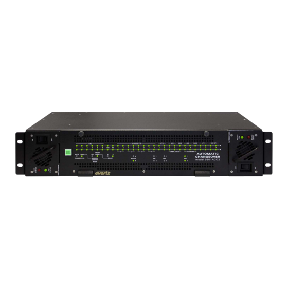
evertz 5601AC02 Instruction Manual (56 pages)
Automatic Changeover
Brand:
evertz
| Category:
Network Hardware
| Size: 1 MB
Table of Contents
Table of Contents
7
Overview
11
Figure 1-1: 5601ACO2 Block Diagram
13
How to Use this Manual
14
Figure 1-2: Front View of Frame
14
Installation
15
Rear Panel
15
Coaxial Connections
15
Figure 2-1: 5601ACO2 Rear Panel
15
Balanced AES, DARS and Analog Audio Connections
16
Linear Time Code, Syncro and GPIO Connections
16
Table 2-1: DARS/AES/ANALOG Terminal Strip Pin Definitions
16
Table 2-2: AUX I/O Pin Definitions
16
Ethernet Connections
17
Table 2-3: ACO CTRL/STATUS and MSC GPIO Terminal Strip Pin Definitions
17
Table 2-4: Standard RJ45 Wiring Colour Codes
17
Power Connections
18
Mounting
18
Power Requirements
18
5601Msc Connections
19
Figure 2-2: Redundant Master Clock/Spg with Auto Changeover System Diagram
19
Sync Outputs
20
10 Mhz Output
20
Word Clock Output
20
Unbalanced DARS AES1 and AES2 Outputs
20
Balanced DARS, AES1, AES2 and Analog Audio Outputs
20
Video Test Signal Generator Outputs
21
LTC and GPIO Connections
21
Synchronizing the Menu Settings of the Two 5601MSC Units
22
Connecting the General Purpose Inputs and Outputs
22
Figure 2-3: Typical GPI Circuitry
22
Figure 2-4: GPO1 Output Circuitry
23
Figure 2-5: GPO2 Output Circuitry
23
How to Operate the Automatic Changeover
25
An Overview of the Status Indicators
25
Operating Mode Indicators
25
Figure 3-1: Model 5601ACO2 Front Panel
25
Input Indicators
26
ACO GPI Indicators
26
Power Supply Indicators
26
Front Panel Control
26
Automatic Changeover Mode
27
Manual GPI Changeover Mode
27
Figure 3-2: Front Panel & Card Edge Control
27
Manual Switch Changeover Mode
28
Front Door Button: Recent Event Trigger
28
Dip Switches
28
GPI Input Mode
28
Table 3-1: DIP Switch Functions
28
Table 3-2: GPI Input Mode Switch Settings
29
Table 3-3: Single GPI Mode Operation
29
Table 3-4: Dual GPI Mode Operation
29
Changeover Rate
30
Bank Priority
30
Change Limiting
30
Table 3-5: Changeover Rate Switch Settings
30
Table 3-6: Bank a Priority Switch Settings
30
Table 3-7: Change Limiting Switch Settings
30
Gpo Tally Outputs
31
Technical Description
33
Auto Changeover Switch Criteria
33
Change Limiting Operation
33
One Change Mode
34
Dual Change Mode
34
Unlimited Change Mode
34
Switching Decision Tree
35
Figure 4-1: 5601ACO2 Switching Logic
35
Specifications
36
LTC Outputs
36
Coaxial Inputs and Outputs
36
Balanced DARS, AES1, AES2 and Analog Audio Inputs and Outputs
36
ACO General Purpose Inputs and Outputs
36
MSC General Purpose Inputs and Outputs
37
Changeover Conditions
37
Ethernet
37
Electrical
37
Physical
37
Upgrading the Firmware
38
Overview
38
Terminal Program Setup
38
Initiating Firmware Upgrade Mode from the Terminal Program
39
Uploading the New Firmware
39
Completing the Upgrade
40
Serial Port Configuration and Status
40
Network Configuration
41
SNMP Configuration
41
Voting Control
42
Show Status
43
Upgrade
44
Vistalink Configuration and Control
45
Connecting the 5601ACO2 to VISTA LINK
45
Installing VISTA LINK
45
Using Vistalink
46
To Configure the 5601ACO2
46
General Control Settings
46
Figure 5-1: Vistalink
46
Configuration - General Control
46
Monitoring the 5601ACO2 Using the General Status Tab
47
Figure 5-2: Vistalink Monitoring - General Status
47
Configuring the Voting Control
48
Global Control Parameters
48
Figure 5-3: Vistalink
48
Monitoring - Voting Control
48
General Parameters
49
Analog TG Voting Parameters
49
HD SDI TG Voting
49
Analog Sync Voting
49
DARS Voting
49
LTC Voting
49
GPO Voting
50
Monitoring the GPO Status
50
GPO Status Tab
50
Figure 5-4: Vistalink Monitoring - GPO Status
50
5601ACO2 Fault Trap Controls
51
Setting the Analog Faults
51
Figure 5-5: Vistalink Monitoring - Analog Faults
51
Setting the 3G HD SDI TG Faults
52
Figure 5-6: Vistalink Monitoring - 3G HD SDI Faults
52
Setting the AES DARS Faults
53
Setting the LTC Faults
53
Figure 5-7: Vistalink Monitoring - AES DARS Faults
53
Setting the MSC GPO Faults
54
Figure 5-8: Vistalink
54
Figure 5-9: Vistalink
54
Monitoring - LTC Faults
54
Monitoring - MSC GPO Faults
54
Configuring the Faults Tab
55
Figure 5-10: Vistalink Monitoring - Faults
55
Advertisement
Advertisement
Related Products
evertz 5600ACO2
evertz 5700MSC-IP
evertz 5600ACO
evertz 5700ACO
evertz 5010-GPSII
evertz 5010-GPSII-VITC
evertz 5950
evertz exponent 500ACO2-HD/SD
evertz 5601MSC
evertz 5600MSC Series
evertz Categories
Media Converter
Network Hardware
Transmitter
Amplifier
Receiver
More evertz Manuals
Login
Sign In
OR
Sign in with Facebook
Sign in with Google
Upload manual
Upload from disk
Upload from URL