
Related Manuals for Acrel AIM-R100


Summary of Contents for Acrel AIM-R100
- Page 1 AIM-R100 Residual Current Monitoring Products Installation and Operation Manual V1.3 Acrel Co., Ltd.
- Page 2 Please read this manual carefully before using these products, in which the involved pictures, logos, symbols, etc. are all reserved by the Acrel Co., Ltd. Personnel not inside the company shall not publicly reprint all or part of the contents without written authorization.
-
Page 3: Table Of Contents
Contens 1 Introduction ..........................1 2 Functional characteristics ......................2 2.1 Function characteristics of AIM-R100 ................2 2.2 Function characteristics of AID150 ..................2 2.3 Function characteristics of ACLP10-24 ................2 2.4 Function characteristics of AKH-0.66/L-20................ 2 3 Reference standards ........................3 4 Technical parameters ........................ -
Page 4: Introduction
The residual current monitoring products are also the monitoring instruments developed by Acrel with rich product design experience and strict reference to the requirements in the standards and specifications. The product conforms to the enterprise standard Q31/0114000129C025-2017 Residual Current Monitoring Device. -
Page 5: Functional Characteristics
When residual current exceeded threshold or connection failure, it provides sound and light alarm function, and it can be eliminated; Up to 16 AIM-R100 residual current monitors or AIM-M10, AIM-M100 insulation monitors can be monitored, wall installation, apply to the operating room, ICU, or other places of centralized monitoring. -
Page 6: Reference Standards
3.2 IEC62020-1:2020 Electrical accessories - Residual current monitors (RCMs) - Part 1: RCMs for household and similar uses 4 Technical parameters 4.1 Technical parameters of AIM-R100 They are shown in Table 2. Table 2 Parameters of AIM-R100 residual current monitor Items parameters AC 220V±10% Voltage Accessory ≤3VA... -
Page 7: Technical Parameters Of Akh 0.66P26/L-20
Rated (secondary) current 50mA Secondary output of transformer Cable line Installation and connection 5.1 Appearance and installation opening size 5.1.1 Appearance and mounting hole size of AIM-R100 Residual current monitor (unit: mm) 11 12 U1 U2 I 2 I 3 COM1 COM2... -
Page 8: Method Of Installation
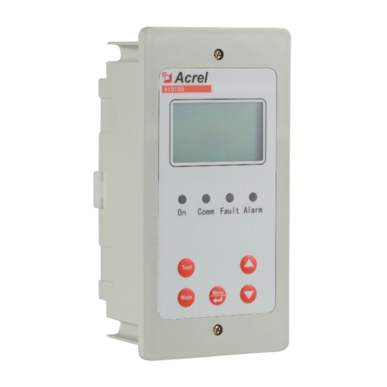
AIM-R100 and AID150 should be connected hand in hand. 5.2.1 Installation method of AIM-R100 residual current monitor The AIM-R100 residual current monitor is installed with guide rail and fixed with buckles, as shown in the figure below:... - Page 9 AID150 centralized alarm and display instrument, which is suitable for embedded wall installation. installation diagram is shown in figure below. 2.Size of wall 3.Insert the shell 1.Product shape openings into the wall Attention: Acrel AID150 As our products are constantly Comm Error Alarm updated, this TEST drawing is for...
-
Page 10: Wiring Method
The ACLP10-24 DC24V power supply is used to install in the way of guide rail, which is fixed with snap-in type. It can also be installed on the same guide rail side by side with the AIM-R100 insulation monitor. 5.3 Wiring method 5.3.1 Wiring method of AIM-R100 residual current monitor... - Page 11 5.3.2 Wiring method of AID150 centralized alarm and display instrument A and B are connected to terminals A and B (15, 16) in AIM-R100.The power terminals shall be connected to the positive pole and ground of the DC24V power supply respectively. The wiring diagram is shown in the figure below.
-
Page 12: Typical Wiring Method
(1) Each residual current monitor can be equipped with at most 12 AKH-0.66/L-20 residual current transformers. (2) Terminals 1 and 2 of the AIM-R100 residual current monitor and terminals 1 and 2 of the power supply of ACLP10-24 DC24V power supply shall be connected to AC220V, which can be directly connected to the bus bar as shown in the figure above, and connected to fuse protection of 6A. -
Page 13: Operation And Usage
AIM-R100, connecting to 100Ω resistance to empty terminal to avoid causing false alarms. (5) terminal 15, 16 of the AIM-R100 residual current monitor and Terminals A and B of AID150 centralized alarm and display instrument can be connected with 2x1.5 mm shielded twisted-pair cable. -
Page 14: Function Description Of Keys
The indicator light flashes and alarms while AIM-R100 or AIM-M 100 has fault “ALARM” When the value of AIM-R100 exceeds the threshold alarm, the indicator light flashes and alarms 6.3 Function description of keys 6.3.1 Key function description of AIM-R100 Residual current monitor Residual current monitor has four buttons, “enter /menu", "", "", "self-check/return". -
Page 15: Key Operation Instructions
6.4 Key operation instructions 6.4.1 AIM-R100 residual current monitor key operation in programming mode (1) Enter the programming mode In normal operation, press the "menu/Enter" key to enter the programming mode password entry page. After entering the correct password, press enter to enter programming mode. The default password is 0001. - Page 16 (8) Enable and close some unused circuits [Circuit Setting] AIM-R100 can be connected to 12 aback-0.66 /L-20 remaining current transformers at most, "circuit setting" can close off the unused part of the circuit that is not connected to the transformer, so as to...
-
Page 17: Communication Protocol
Press Up and Down to L1: Open L2: Close Clr SOE Sw Info. select the option L3: Close L4: Close Set Loop Language Press Enter to confirm Press Up,Down and Enter to set value, press Esc to save or exit Press Up and Down to select the option Clr SOE... -
Page 18: Introduction To Function Code
equipment, but does not allow data exchange between independent terminal equipment, so that terminal equipment will not occupy the communication line when they are initialized, but only respond to the query signal arriving at the machine. 7.2 Introduction to function code 7.2.1 Function code 03H or 04H: register read This function allows users to obtain data and system parameters collected and recorded by the device. -
Page 19: Aim-R100 Communication Address Table
0006Hdata for High byte sending Low byte High byte CR code Low byte 7.3 AIM-R100 communication address table NO. Address parameters Read/write Range Data Type 0000H Password 0001~9999; default 0001 Address 1~16; default 1 0001H Baud Rate 1~3:4800,9600,19200bps; default 2... - Page 20 loop 3 state (Same as above) 2bit loop 4 state (Same as above) 2bit loop 5 state (Same as above) 2bit loop 6 state (Same as above) 2bit loop 7 state (Same as above) 2bit loop 8 state (Same as above) 2bit 000CH Fault Flag...
-
Page 21: Typical Applications
5.4 of this manual, the inspection can be carried out in the following order: (1) Check each set of residual current monitoring system, including AIM-R100 residual current monitor, AKH0.66/l-20 residual current transformer, AID150 centralized alarm and display instrument, and ACLP10-24 DC24V power supply which supply power for AID150. -
Page 22: Common Faults And Eliminations
Make sure the wirings are correct and power on the system. Then check whether each meter is abnormal, and whether there is a fault alarm in AIM-R100. For common problems, the causes can be determined and the faults can be eliminated according to the phenomenon of each instrument and the fault types:... - Page 23 instruments hand in hand. After setting, the head and end of the communication bus are connected in parallel with a matching resistor of 120Ω (the resistance must be added, otherwise communication may not be possible). AID150 does not require additional setting of RS485 communication address. (4)When AID150 is used, the total number of residual current monitors or insulation monitors connected to RS485 bus should be set first, and the total number should not exceed 16 sets.
- Page 24 Address: No.253 Yulv Road Jiading District, Shanghai,China TEL.: 0086-21-69158338 0086-21-69156052 0086-21-59156392 0086-21-69156971 Fax: 0086-21-69158303 Web-site: www.acrel-electric.com E-mail: ACREL008@vip.163.com Postcode: 201801 Manufacturer: Jiangsu Acrel Electrical Manufacturing Co., LTD. Address: No.5 Dongmeng Road,Dongmeng industrial Park, Nanzha Street,Jiangyin City,Jiangsu Province,China TEL./Fax: 0086-510-86179970 Web-site: www.jsacrel.com Postcode: 214405 E-mail: JY-ACREL001@vip.163.com...
Need help?
Do you have a question about the AIM-R100 and is the answer not in the manual?
Questions and answers