
Related Manuals for Acrel AIM-M300


Summary of Contents for Acrel AIM-M300
- Page 1 Medical IT System Insulation Monitoring and Fault Locating Devices (Six-Piece Set) Installation and Operation Manual V1.0 Acrel Co., Ltd.
- Page 2 Please read this manual carefully before using these series of products. In this manual, all pictures, logos, symbols, etc. are all reserved by the Acrel Electric Co., Ltd. Personnel not inside the company shall not publicly reprint all or part of the contents without written authorization.
-
Page 3: Table Of Contents
1 Introduction ............................1 2 Function features ..........................3 2.1 Function features of AITR series medical isolation transformer ....... 3 2.2 Function features of AIM-M300 series medical intelligent monitoring device ................................3 2.3 AIL150-4/AIL150-8/AIL160-6 insulation fault locator ..........3 2.5 Function features of AID150 centralized alarm and display device ....3 2.6 Function features of HDR-60-24 power supply device .......... - Page 4 6.2 LED indicator instructions ..................... 20 6.3 Button function descriptions ..................21 6.4 Button operation descriptions ..................22 7 Communication protocol ......................... 27 7.1 Modbus-RTU communication protocol ................27 7.2 CAN communication description ..................31 8 Typical applications ........................34 8.1 Applications of insulation monitoring and fault locating six pieces of products in ICU/CCU .............................
-
Page 5: Introduction
Medical insulation monitoring and fault locating device is developed by Acrel with many years’ design experience, according to the special requirements of the insulation monitoring and fault locating of the power distribution system in Class 2 medical locations. - Page 6 The AKH-0.66P26 type current transformer is the protective current transformer supporting the AIM-M300 series insulation monitor, of which the maximum measurable current AKH-0.66P26 current transformation ratio 2000:1. current transformer transformer is directly fixed inside cabinet by...
-
Page 7: Function Features
The CAN bus technology is used to exchange data with other equipment. Cooperate with AIM-M300/SG to realize fault locating function, in which the AIL150-4 locates 4 channels , AIL150-8 locates 8 channels. And AIL160-6 locates 6 channels in all. -
Page 8: Function Features Of Hdr-60-24 Power Supply Device
AC 220V input, DC 24V output, with max output power of 60W; Used for the DC 24V power supply for AIM-M300 series medical intelligent insulation monitoring device, AIL150/AIL160 series insulation fault locator, AID150 centralized alarm and display device and other devices. -
Page 9: Technical Parameters
16: Special requirements for isolation transformers for power supply in medical locations 4 Technical parameters 4.1 Technical parameters of AITR series medical isolation transformer Refer to Table 2. Table 2 Technical Parameters of AITR Series of Medical Isolation Transformer Type AITR10000S AITR8000S AITR6300S... -
Page 10: Monitoring Device
4.2 Technical parameters of AIM-M300 series medical intelligent insulation monitoring device Refer to Table 3. Table 3 Technical Parameters of AIM-M300 series Medical Intelligent Insulation Monitoring AUX Power Voltage DC 18…36V Thermal 2 Pt100 resistor Power ≤6W Measuring Temperature -50…+200℃... -
Page 11: Technical Parameters Of Ail150-4/Ail150-8 /Ail160-4Test Signal Generator
Measuring voltage ±12V Measuring current ≤50 Note: AIM-M300 insulation monitoring device doesn’t support locating function. When need fault locating function, please select AIM-M300/SG. 4.3 Technical parameters of AIL150-4/AIL150-8 /AIL160-4test signal generator Refer to Table 4. Table 4 Technical Parameters ofAIL150-4/AIL150-8/AIL160-6... -
Page 12: Technical Parameters Of Hdr-60-24 Power Supply Device
Alarm type Insulation fault, overload, and over temperature Communication mode RS485,MODBUS-RTU Display mode LCD display,128*64 dot array 4.5 Technical parameters of HDR-60-24 power supply device Refer to Table 6. Table 6 Technical Parameters of HDR-60-24 Power Supply Device Type Input Output Installation HDR-60-24... - Page 13 69±5 AITR5000S 5000 11*18 62±5 AITR3150S 3150 11*18 49±5 5.1.2 Dimensions of AIM-M300 series medical intelligent insulation monitoring device (unit: mm) Front view Side view 5.1.3 Dimensions of AIL150-4/AIL150-8 /AIL160-6 insulation fault locator (unit: mm) Acrel Acrel Acrel Acrel Acrel...
- Page 14 Front view Side view Note: AIL150-4 and AIL150-8 these two types take the same product shell, so their external dimensions are exactly the same. 5.1.4 Dimensions of AID150 centralized alarm and display device (unit: mm) Acrel AID150 Comm Test Menu...
-
Page 15: Installation
If the isolation transformer is installed separately, it is not suitable to put it too far away from the AIM-M300 series insulation monitor. If the AID150 centralized alarm and display device is used in the operation room, it can be embedded in the wall of the operating room next to the intelligence panel, so that the medical staff can view conveniently. - Page 16 1) If you choose to embed the wall for installation, the installation diagram is as follows: 2.Size of wall 3.Insert the shell 1.Product shape openings into the wall Attention: Acrel AID150 As our products are constantly Comm Error Alarm updated, this TEST...
-
Page 17: Wiring Method
The S terminal is connected to the PE bus bar on the spot (or the equipotential terminal line). Two ST terminals are temperature sensor interfaces, which are respectively connected to the No.11 and 12 terminals of AIM-M300 series insulation monitoring device. Figure 2 AITR series medical isolation transformer terminal blocks diagram... - Page 18 5.3.2 Wiring mode of AIM-M300(or AIM-M300/SG) 24V, G for the auxiliary power supply, and L1, L2 are connected to the IT system (which can be connected to the two output terminals of isolation transformer). I0, I1 for the current transformer signal input, and T0, T1 as the temperature sensor signal input.
- Page 19 power supply can select 2×1.5mm copper wires, and the L1 and L2 terminals corresponding to the No.4 and 5 can select 2×1.5mm multistrand copper wires, and the FE and KE terminals corresponding to the No.13 and 14 can select 2×1.5mm yellow-green wires (grounding wires).
-
Page 20: 1Typical Wiring Diagram
5.3.5 Wiring mode of AID150 centralized alarm and display device A and B terminals are connected with A and B in the lower terminal of AIM-M300. The terminals of the power supply correspond to the positive pole and ground of the 24V DC power supply respectively. - Page 21 6A fuse. 3) The relay output of the AIM-M300 sereis insulation monitor(No.21 and 22 terminals) is a dry node, which needs an additional fan power supply when used for the fan control. When multiple transformers...
-
Page 22: Note
CAN bus One matching resistor shall be connected in parallel between the two communication terminals. The recommended resistance value is 120 Ω. Terminals 13 and 14 of AIM-M300(or AIM-M300/SG) are RS485 communication terminals, which are used to communicate with AID150. -
Page 23: Programming And Application
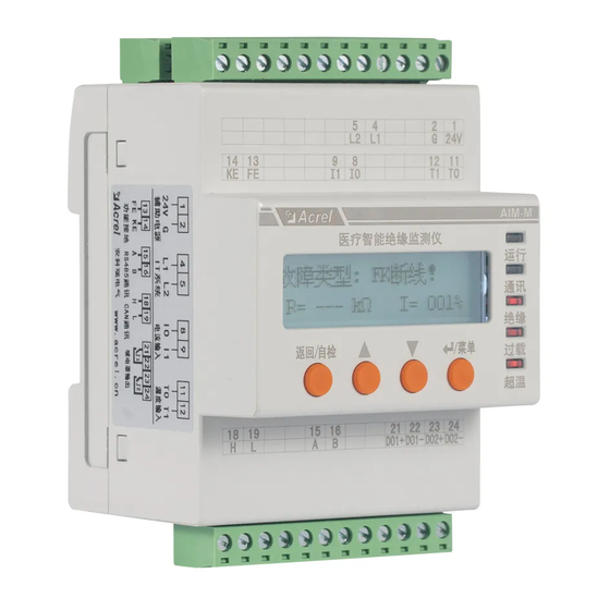
15 16 21 22 23 24 AIM-M300 series medical intelligent insulation monitoring device panel 6.1.2 Dial switch description of AIL160-6 insulation fault locator Open the cover plate on the panel, there are ten dial switches in it. Functions of each dial switch are showed in the following table. -
Page 24: Led Indicator Instructions
48 channels in all. 6.2 LED indicator instructions 6.2.1 LED indicator instructions of AIM-M300 series medical intelligent insulation monitoring device Indicator Instructions When the device operation is normal, the indicator light flashes, with the flashing frequency of about one time per second. -
Page 25: Button Function Descriptions
6.3 Button function descriptions 6.3.1 Button function descriptions of AIM-M300 sereies medical intelligent insulation monitoring device AIM-M300 has four buttons in total, namely the “Set and Enter” shared button, “” Up button, “”Down button, and “Test” button. Buttons Button function... -
Page 26: Button Operation Descriptions
In the main interface, view the version information of the software by pressing the "Down button" twice consecutively. (4) Register address (CAN communication address) to AID200. When AIM-M300 series IMD and AID200 are used together, if AIM-M300(or AIM-M300/SG) doesn’t successfully register address to AID200, the manual registration is required. - Page 27 to enter other settings item, then change the password number by "Up " or "Down " button, then press "Enter" button to confirm it. Press "Return" button to save and exit programming mode. Examples of operations are as follows: Input the password UP/DOWN Input the password 2012-10-10...
- Page 28 (5) Communication settings Communication settings include RS485 communication settings and CAN communication settings. The RS485 Communication settings include settings of the communication address and communication baud rate, and CAN communication settings mean to set the communication address, which can also set whether the device is supporting the use of fault locator.
- Page 29 Loc.:OR Room:06 System normal Loc.:ICU Bed:04 L1:OK L2:OK Fault type:Insu L3:OK L4:ORC 2015-07-02 12:30:45 Normal system fault indication(AIM-M300) fault indication(AIM-R100) 2)Fault record viewing interface operations and descriptions -------------------- -------NO.01-------- -------------------- Press up and Check fault System normal Press Enter Loc.:ICU Bed:04 down key Press Enter>>>...
- Page 30 -------------------- -------------------- Press Up and Down to input password Input password: Press MENU System normal 0000 Press Enter to confirm -------------------- 2015-07-02 12:30:45 -------------------- Password Time Press Erasure to return Slave Comm Clear Firmware -------------------- -------------------- Save param settings? Press Up and Down to select YES or NO Press Enter to confirm -------------------- --------------------...
-
Page 31: Communication Protocol
7.1 Modbus-RTU communication protocol 7.1.1 Introduction In six pieces of products, the communication between the AIM-M300(or AIM-M300/SG) insulation monitor and the upper computer by the Modbus-RTU communication protocol. The Modbus protocol particularly defines the check code, the data sequences and so on, which are the necessary contents of the specific data exchange. - Page 32 High CRC check byte byte code Low byte 7.1.2.2 Function code 10H: Write the registers The function code 10H allows the user to change the contents of multiple registers, which can write the time and date in this meter. The host can write up to 16 (32 bytes) data at a time. The following example shows a preset address of 01 with an installation date and time of 12:00, Friday, December 1 , 2009, in which the Monday to Sunday are replaced with number 1 to 7.
- Page 33 High byte CRC check code byte 7.1.3 Parameter address table in AIM-M300 series medical intelligent insulation monitoring device Read-write Data Address Parameter Value range property type 0000H Protecting 0001-9999 (Default value is Word passwords 0001) 0001H high RS485 1~247 (Default value is 1)
- Page 34 0006H high Hour 0-23 byte Word 0006H low Minute 0-59 byte 0007H high Second 0-59 byte Word 0007H low Reserve byte 0008H Insulation 10-999(Unit is KΩ) Word resistance 0009H Load current 0-500(Unit is 0.1A) Word 000AH Transformer 40-140(Unit is℃) Word temperature 000BH high Fault circuit...
-
Page 35: Can Communication Description
7.2 CAN communication description 7.2.1 Introduction Among the six pieces of products, the AIM-M300 series insulation monitor, AIL150/AIL160 series fault locator form a can communication subsystem. Their address is the same address, and they are distinguished by identification. The communication rate is 400kbps. - Page 36 The data frames stipulated in the CAN communication protocol have two formats, which are standard format and extended format, and the arbitration segments of the two formats are different. Acrel AIM-M300/SG insulation monitors uses the standard format, of which the arbitration segment has 11 bits.
- Page 37 7.2.3.1 Startup command 01 01 Description: When the AIM-M300 series insulation monitoring device monitors the insulation faults in the isolated power system, it will issue a startup command to initiate the AIL150-4/8 fault locator. After receiving this command, the AIL150-4/8 fault locator begins the insulation fault locating.
-
Page 38: Typical Applications
AIL160-6 2) When setting CAN address, it is only needed to set the CAN address of AIM-M300 series IMD to any value between 1 to 110 after the 4 meters are on a unified power, then save the value and the CAN address of AIL150 can be simultaneously set the same with address of AIM-M300(or AIM-M300/SG). -
Page 39: Powerup And Debugging Instructions
4) Check whether the No.11(T0) and 12 (T1) terminals of AIM-M300 series IMD in each system are reliably connected to the two ST terminals of the isolation transformer. -
Page 40: Common Faults And Eliminations
Make sure the wirings are correct and power on the system. Then check whether each device is abnormal, and whether there is a fault alarm in AIM-M300 series device. For common problems, the causes can be determined and the faults can be eliminated according to the phenomenon of each device... -
Page 41: Settings And Debugging
9.3 Settings and debugging 1) After the system is powered on, set the AIM-M300(or AIM-M300/SG) load current alarm value according to the capacity of the isolation transformer. The corresponding relations between alarm current and isolation transformer capacity are: 45A---10kVA, 35A---8kVA, 28A---6.3kVA, 14A---3.15kVA. - Page 42 2) Open the AIM-M300 series IMD fault locating function. Enter the the communication settings menu and set the LOCAT item to YES, then quit and save to start this function. 3) Address settings. To ensure the realization of fault location function, it is necessary to set the can communication address of AIM-M300 series IMD, and set the can communication address of AIL150/AIL160 through this operation.
Need help?
Do you have a question about the AIM-M300 and is the answer not in the manual?
Questions and answers