Acrel AID120 Installation And Operation Manual
Hide thumbs
Also See for AID120:
- Installation and operation manual (42 pages) ,
- Installation and operation manual (34 pages)

Related Manuals for Acrel AID120


Summary of Contents for Acrel AID120
- Page 1 Medical IT System Intelligent Insulation Monitoring Devices (5-Piece Set) Installation and Operation Manual V2.6 Acrel Co., Ltd.
- Page 2 Declaration Please read this instruction carefully before using this product. All pictures, logos and symbols involved are owned by Acrel Co., Ltd. All or part of the content shall not be reproduced publicly without written authorization by non-company personnel. Please read the instructions and precautions in this operation manual carefully before using this series of products.
- Page 3 Remove discontinued models from the five-piece set and 2020.04.01 V2.3 make adjustments and updates where necessary. 2020.06.11 V2.4 Added panel installation schematic for AID120/150. 2020.08.14 V2.5 Correct errors and omissions, adjust the wording. Adjust format, logo update, transformer update, reference standard...
-
Page 4: Table Of Contents
2.1 Function features of AITR series medical isolation transformer ........2 2.2 Function features of AIM-M100 ..................2 2.3 Function features of AID120/150 ................... 3 2.4 Function features of ACLP10-24 ..................3 2.5 Function features of AKH-0.66P26 current transformer ..........3 3.Reference standard ......................... -
Page 5: Introduction
Insulation monitoring products of medical IT system (5-piece set) include AITR series medical isolation transformer, AIM-M100 medical intelligent insulation monitor, AKH-0.66P26 current transformer, ACLP10-24 dc power module and AID series (AID120, AID150) external alarm and display instrument, etc., as shown in Table 1. -
Page 6: Function Features
Special DC module for instrument, stable output voltage. ACLP10-24 The module adopts the standard guide way to install, and can DC power module be installed on the same guide way with the insulation monitor, easy to install. It is suitable for wall installation embedded in operating room or nurse station and can monitor 1 AIM-M100 insulation monitor. -
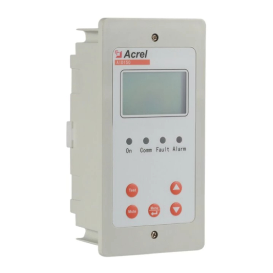
Page 7: Function Features Of Aid120/150
2.3 Function features of AID120/150 ➢ The insulation resistance alarm value, load current alarm value and transformer temperature alarm value of the system can be set remotely. ➢ When the system appears insulation fault, overload, transformer temperature over limit and wiring fault, alarm and display instrument gives out the corresponding sound and light alarm, and has the function of eliminating sound alarm. -
Page 8: Technical Parameters
4 Technical parameters 4.1 Technical parameters of AITR series medical isolation transformer Refer to Table 3. Table 3 Technical Parameters of AITR Series of Medical Isolation Transformer Type AITR10000 AITR8000 AITR6300 AITR5000 AITR3150 Insulation class Protection class IP00 IP00 IP00 IP00 IP00 Power/voltage/... -
Page 9: Technical Parameters Of Aid120/Aid150
Measuring Conform to IEC ≤±5% compatibility accuracy 61326-2-4 / Electromagnetic radiation 4.3 Technical parameters of AID120/AID150 Refer to Table 5. Table 5 Technical parameters of AID120 / 150 Parameter Type AID120 AID150 Voltage DC 24V Auxiliary power supply Consumption < 0.6W ——... -
Page 10: Technical Parameters Of Aclp10-24
4.4 Technical parameters of ACLP10-24 Refer to Table 6. Table 6 Technical parameters of ACLP10-24 Input voltage AC 220V (± 10%) Frequency 50/60Hz Power Output voltage DC 24V± 5% ≤30% Voltage regulation factor ≤20℃ Temperature rise Dielectric intensity 4000V AC/minute 4.5 Technical parameters of AKH-0.66P26 current transformer Refer to Table 7. - Page 11 1 2 3 4 5 6 7 Acrel DC Power Supply ACLP10-24 Type:ACLP10-24 Input:AC 220± 10% 50-60Hz Output:DC 24V 0.125A DC ON www.acrel.cn 8 9 10 11 12 13 14 Front view Side view 5.1.4 External dimensions of AID120/AID150 (unit:mm) 7 / 29...
-
Page 12: Installation Method
Acrel Insulation resistance kΩ Test Mute Insulation Transformer load rate % Overload Menu Overtemp AID120 AID120 Front view AID120 Side view AID120 Hole size Acrel AID150 Comm Fault Alarm Test Menu Mute AID150 Front view AID150 Side view AID150 Hole size 5.1.5 External dimensions of AKH-0.66P26 current transformer (unit: mm) - Page 13 AID120 / 150 external alarm and display device shell is the same, just display and installation direction is different. (1) If you choose to embed the wall for installation, taking AID120 as an example, the installation diagram is as follows:...
-
Page 14: Wiring Method
TEST Erasure constantly updated, Insulation Transformer load rate % Overload this drawing is for MENU Overtemp AID120 reference only until 4.Connect the Screw it has been connection wire to the confirmed by the 5.Fixed panel and panel through the shell relevant personnel. - Page 15 connected to external field load. The S terminal is connected to the PE bus bar on the spot (or the equipotential terminal line). Two ST terminals are temperature sensor interfaces, which are respectively connected to the No.11 and 12 terminals of AIM-M100 insulation monitoring instrument. Power Input Grounding temperature Powe Output...
- Page 16 19. The COM port for communication does not need wiring. 5.3.3 Wiring mode of AID120 / 150 centralized alarm and display instrument A and B relate to A2 and B2 in the lower terminal of AIM-M100. The terminals of the power supply correspond to the positive pole and ground of the 24V DC power module respectively.
-
Page 17: Typical Wiring Diagram
connected with A1 and A4 is connected with A2. 8 and 9 (V1, G), 10 and 11 (V2, G), 13 and 14 (V3, G), these are three groups of 24 V power output, which are used to provide DC power supply for external alarm and display instrument of AID series. -
Page 18: Considerations
the two wires. The output is connected with the 2× 1.5mm wire to the No.8, 9 terminals of AIM-M100, which is not allowed for grounding. (5) In order to reliably monitor the grounding insulation of the isolation power system, the No.4, 5 terminals of AIM-M100 insulation monitor should be reliably connected to IT system (which can be connected in parallel to the output terminal of the isolation transformer) with 2×... -
Page 19: Programming And Application
Acrel Medical Intelligent Insulation Monitor AIM-M100 Insulation Overload Overtemp Operation Key Menu Test Terminal *12 (2) AID120 External alarm and display panel LED Indicator Acrel LCD Display Insulation resistance kΩ Test Mute Installed Screw Insulation Operation Key Transformer load rate %... -
Page 20: Led Indicator Instructions
When testing transformer temperature exceeds the alarm value, or when the Overtemp temperature sensor wiring is disconnected, the indicator light flashes to alarm. 6.2.2 AID120 Indicator Instructions When the device is in normal operation, the indicator flashes, and the flickering frequency is about once a second. -
Page 21: Button Function Descriptions
Self-test button In operation state, used to start the self-test function of instrument. 6.3.2 AID120/150 The centralized alarm and display instrument has five buttons in total, namely the "Mute" button, "Menu & Enter" shared button, "▲" Up button, "▼" Down button, and "Test" button. - Page 22 "ENTER" key again to enter the programming mode. (2) Exit programming mode. In the programming mode, select the option [1. Exit] through the up and down keys, and press the "enter" key to exit the programming mode and enter the operation mode.
- Page 23 5.Comm. set 1.Exit 3.BAUD1 :9600 6.Relay set 2.Address1 :000 4.Address2 :001 Note: when AIM-M100 communicates with AID120, the slave address of AIM-M 100 must be set to 1, and the slave baud must be set to 9600. 19 / 29...
- Page 24 6.4.3 AID120 external alarm and display key operation (1) AID120 has 5 seconds to read the host data by default when the AID120 is started. At this time, the insulation resistance value and transformer load rate display the initial value of 0. If the host data is not read for five consecutive times, the insulation resistance shows err, the transformer load rate shows err, at the same time, the sound alarm is started and all LED flickers.
- Page 25 无 Software version number 6.4.5 AID120 programming example (1) Insulation resistance value setting. Taking 50kΩ alarm value setting as an example, the setting steps are as follows: (2) Current alarm value setting. Taking the current alarm value 45A as an example, the setting is as follows: (3) Setting of transformer temperature alarm value.
- Page 26 6.4.6 AID150 (1) Description of the Operating Interface After the system is powered on, if there is no fault alarm, AID150 shows the normal operation interface as shown in the following figure. The black boxes in the figure indicate that the corresponding address serial number is connected to the instrument communication, and the black boxes indicate that there is no instrument connection, or that the communication is not connected.
- Page 27 -------------------- -------------------- Input password: Press Up and Down to input password Press MENU System normal 0000 Press Enter to confirm -------------------- 2015-07-02 12:30:45 -------------------- Password Time Press Erasure to return Slave Comm Clear Firmware -------------------- -------------------- Save param settings? Press Up and Down to select YES or NO Press Enter to confirm -------------------- --------------------...
-
Page 28: Communication Protocol
Note: when AID150 is in use, the total number of Insulation Monitors and residual current monitors connected to RS485 bus should be set first, and the total number should not exceed 16 sets. This parameter is in [communication settings] in the menu. The slave address of each insulation monitor and residual current monitor shall be numbered from 1 to 16 as far as possible. -
Page 29: Aim-M10 Parameter Address Table
Function code Function code High byte High byte Start address Start address Low byte Low byte Number of High byte Number of High byte registers registers Low byte Low byte Number of registers Low byte CRC check code High byte High byte 0004H data Low byte... - Page 30 0007H high Second R/W 0~59 word 0007H low Reserve 0008H Insulation resistance R/W 10~999 (Unit is kΩ) word 0009H Load current R/W 0~500 (Unit is 0.1A) word 000AH Transformer R/W -50~200 (Unit is℃) word temperature 000BH high Reserve 000BH low Fault type Bit0: 0 normal;...
-
Page 31: Typical Applications
Central Intelligence Control Panel C65H ICB 16A/2P Operating Bed C65H ICB 16A/2P PC Platform RS485 Alarm and display instrument ACLP10-24 AIM-M100 AID120 (Installed in operating room) DC power DC 24V DTSF1352 BG3-63II/N4DR Interpact AC220/24V(isolation transformer inside) INS 63A C65N C16/2P... -
Page 32: Common Faults And Eliminations
series external display device, and the positive and negative poles are correct. (3) Check whether 8(I0) and 9(I1) terminals of AIM-M100 in each system are reliably connected to the terminals of the transformer AKH-0.66P26 socketed to the secondary side of the corresponding isolation transformer, and are not grounded. -
Page 33: Settings And Debugging
Note: If faults occur, interrupt the power to troubleshoot, and adjust the wirings until everything is normal. 9.3 Settings and debugging (1) When entering the menu settings, ACREL medical IT products need to enter the password. The initial password of all medical IT products is 0001. - Page 34 Address: No.253 Yulv Road Jiading District, Shanghai,China TEL.: 0086-21-69158338 0086-21-69156052 0086-21-59156392 0086-21-69156971 Fax: 0086-21-69158303 Web-site: www.acrel-electric.com mail: ACREL008@vip.163.com Postcode: 201801 Manufacturer: Jiangsu Acrel Electrical Manufacturing Co., LTD. Address: No.5 Dongmeng Road,Dongmeng industrial Park, Nanzha Street,Jiangyin City,Jiangsu Province,China TEL:0086-510-86179966 Fax:0086-510-86179975 Web-site: www.jsacrel.com Postcode: 214405 E-mail: sales@email.acrel.cn...
Need help?
Do you have a question about the AID120 and is the answer not in the manual?
Questions and answers