
Subscribe to Our Youtube Channel
Related Manuals for Acrel AITR Series


Summary of Contents for Acrel AITR Series
- Page 1 Medical IT System Insulation Monitoring Devices (Four-Piece Set) Installation and Operation Manual V2.5 Acrel Co., Ltd.
- Page 2 Please read this manual carefully before using this series of products, in which the involved pictures, logos, symbols, etc. are all reserved by the Acrel Electric Co., Ltd. Personnel not inside the company shall not publicly reprint all or part of the contents without written authorization.
- Page 3 更 改 履 历 Number Revision Versions after Reasons for revision of times date revision On the basis of the original insulation monitoring products, the contents of all five pieces of 2016.1.20 V2.0 products are integrated to replace the instructions of each sub-product. 2016.10.25 V2.1 Some errors have been fixed...
-
Page 4: Table Of Contents
Contents 1 Introduction ........................... 1 2 Function features ......................... 2 2.1 Function features of AITR series medical isolation transformer ......2 2.2 AIM-M10 medical intelligent insulation monitor ............2 2.3 Function features of AID10/150 ..................3 2.5 Function features of AKH-0.66P26 current transformer ........... 3 3. - Page 5 8.1 Application of four-piece set of medical IT system insulation monitoring products in operating room ..................... 26 9 Power on and debugging instructions ................27 9.1 Wiring check ......................... 27 9.2 Common faults and eliminations ..................28 9.3 Settings and debugging ..................... 29...
-
Page 6: Introduction
IT System Insulation Monitor provisions. Insulation monitoring products of medical IT system (four-piece set) include AITR series medical isolation transformer, AIM-M10 medical intelligent insulation monitor, AKH-0.66P26 current transformer and AID series (AID10, AID150) external alarm and display instrument, etc., as shown in Table 1. -
Page 7: Function Features
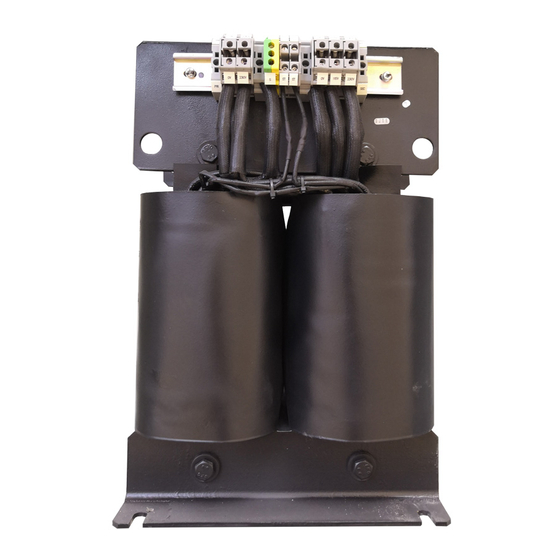
AID150 be remote. The AID150 can also monitor data from multiple AIM-R100 residual current monitors. 2 Function features 2.1 Function features of AITR series medical isolation transformer The transformation ratio between the primary and secondary windings is 1:1. ... -
Page 8: Function Features Of Aid10/150
MODBUS-RTU, which communicates with external alarm and display instrument, can monitor the operation of IT system remotely; Event record, including the time and type of the alarm, is convenient for the operator to analyze the operation status of the system and eliminate the fault in time; ... -
Page 9: Technical Parameters
16: Special requirements for isolation transformers for power supply in medical locations 4 Technical parameters 4.1 Technical parameters of AITR series medical isolation transformer Refer to Table 3. Table 3 Technical Parameters of AITR Series of Medical Isolation Transformer Type AITR10000 AITR8000... -
Page 10: Technical Parameters Of Aim-M10 Medical Insulation Monitor
parameters Fuse wire Primary winding <55mΩ <64mΩ <80mΩ <131 mΩ <245mΩ resistance Secondary <45mΩ <64mΩ <80mΩ <116 mΩ <228mΩ winding resistance Iron loss <150W <105W <107W <77W <55W Copper loss <230W <200W <170W <125W <120W Efficiency >96% >96% >96% >96% >95% Maximum ambient <40℃... -
Page 11: Technical Parameters Of Aid10/Aid150
temperature Response <2s Storage temperature -20—+70℃ time Measuring 5%-95%, <12V Relative humidity voltage non-condensate Measuring <42uA Altitude ≤2500m current Measuring RS485 interface, 2.1-50A Communication range Modbus-RTU Load current Rated impulse voltage/pollution Alarm value 5-50A 4KV/Ⅲ degree Measuring Conform to IEC ≤±5% EMC/EMR accuracy... -
Page 12: Installation And Wiring
5.1 Shape and mounting hole size 5.1.1 External dimensions of AITR series medical isolation transformer (unit: mm) Shape structure and size of AITR series medical isolation transformer are shown as below and in Table 7 (unit: mm) External dimensions of AITR series medical isolation transformer... - Page 13 Acrel Acrel AIM-M10 AIM-M10 Insulation Overload Overtemp Test Front view Side view Bottom view 5.1.3 External dimensions of AID series(unit: mm) AID10 Overload Overtemp Insulation Test Mute AID10 front view AID10 hole size AID10 side view A c r e l...
-
Page 14: Wiring Method
Two ST terminals are temperature sensor interfaces, which are respectively connected to the No.17 and 18 terminals of AIM-M10 insulation monitoring instrument. Figure 2 AITR series medical isolation transformer terminal blocks diagram Note: The wirings of input and output terminals of the isolation transformer should select the copper wires matching the line diameter based on the isolation transformer rated input and output current (refer to tables in section 5.4). - Page 15 J1, J2 (7,8) are output of over temperature alarm relay (used to control cooling fan). Upper terminal: L1, L2 (11, 12) are connected with monitored it system. I0, I1 (15, 16) are signal input of current transformer akh-0.66p26. T0, T1 (17, 18) are signal input of temperature sensor. Note: 为用于CT二次侧短接的试验端子...
-
Page 16: Installation Method
supply correspond to the positive pole and ground of the 24V DC power module respectively. The wiring diagram is shown in the following figure. RS485 communication Auxiliary power supply The 24V power supply can be connected by multiple copper wires of 2 x 1.5mm2, and the RS485 communication terminal can be connected by shielded twisted pair of 2 x 1.5mm2. - Page 17 5.3.2 Installation mode of AID series alarm and display instrument 1)If AID10 is embedded into the wall, the standard 86*86 mounting hole shall be reserved in advance. The installation diagram is as follows: 86 boxes and walls Lower shell assembly 1)Separate the upper 2)Connect the connecting wire and lower shell of...
- Page 18 2.Size of wall 3.Insert the shell 1.Product shape openings into the wall Attention: Acrel AID150 As our products are constantly Comm Error Alarm updated, this TEST drawing is for MENU reference only until it has been confirmed by the 5.Fixed LCD board 4.Connect to the...
-
Page 19: Typical Wiring Diagram
5.4 Typical wiring diagram AID10 Overload Overtemp Insulation Mute Test Note: 1) The connection line diameter of the input and output of the isolation transformer should match the rated current of the isolation transformer, or it can be selected according to the following table: Isolation transformer type Selected line diameter... -
Page 20: Considerations
12 terminals of AIM-M10 insulation monitor should be reliably connected to IT system (which can be connected in parallel to the output terminal of the isolation transformer) with 2×1.5mm multicore copper wires, and the No.1, 2 terminals should be respectively connected to the on-site equipotential terminals (or the grounding terminals in the isolation power cabinet) with two independent 4mm yellow-green grounding wires. -
Page 21: Programming And Application
If the circuit breaker selection is not in accordance with the above requirements, the company shall not be liable for any medical malpractice caused by the closure difficulty of the circuit breaker or the disconnection of the circuit breaker during operation. 6 Programming and application 6.1 Panel description of AIM-M10 Acrel Acrel AIM-M10 AIM-M10 Insulation... -
Page 22: Button Function Descriptions
Overtemp When testing transformer temperature exceeds the alarm value, or when the temperature sensor wiring is disconnected, the indicator light flashes to alarm. 6.2.2 AID10 Indicator status Instructions When the device is in normal operation, the indicator flashes, and the flickering frequency is about once a second. -
Page 23: Button Operation Descriptions
In programming mode, used as the Enter button. Up button, In non-programming mode, used to view the fault records. Down button In programming mode, used to increase or decrease the values, or to change the protection action status Self-test button. In operation state, used to start the self-test function of instrument. - Page 24 simulate overload fault, insulation fault and over temperature fault. In order to detect and judge whether the main fault is normal or not. If the monitor can detect the above three kinds of faults, it indicates that the instrument function is normal. 6.4.2 AIM-M10 insulation monitor in programming mode (1)Enter programming mode In normal operation, press Enter to enter the password input page of programming mode.
- Page 25 "no" by Up and Down keys, and the flashing indicates the selection. Press the "Enter" key to save the parameters or not, exit the programming mode and enter the operation mode. 自检键 ℃ Ω 6.4.3 AID10 alarm and display key operation (1) After AID10 and AIM-M10 are connected through RS485 communication, the On light flashes, indicating that the communication is normal.
- Page 26 -------------------- -------NO.01-------- -------------------- Press up and Check fault System normal Press Enter Loc.:ICU Bed:04 down key Press Enter>>> Type:insulation -------------------- Time:15-01-01 16:32 2015-07-02 12:30:45 -------NO.03-------- Press Erasure to return Press up and down key Slave addr.:00 Type:No record Time:00-00-00 00:00 3) Programming Interface Operation and Explanation The operation method and process are shown in the following flow chart.
- Page 27 -------------------- -------------------- Press Up and Down to input password Input password: Press MENU System normal 0000 Press Enter to confirm -------------------- 2015-07-02 12:30:45 -------------------- Password Time Press Erasure to return Slave Comm Clear Firmware -------------------- -------------------- Save param settings? Press Up and Down to select YES or NO Press Enter to confirm -------------------- --------------------...
-
Page 28: Communication Protocol
when aid150 is in use, the total number of Insulation Monitors and residual current monitors connected to RS485 bus should be set first, and the total number should not exceed 16 sets. This parameter is in [communication settings] in the menu. The slave address of each insulation monitor and residual current monitor shall be numbered from 1 to 16 as far as possible. - Page 29 data byte High Number of byte byte register High Low byte CRC check byte code High CRC check byte byte code Low byte 7.2.2 Function code 10H: Write the registers The function code 10H allows the user to change the contents of multiple registers, which can write the time and date in this meter.
-
Page 30: Aim-M10 Parameter Address Table
byte High 0006H byte Data to be written byte High CRC check byte code byte 7.3 AIM-M10 parameter address table Read-writ Address Parameter Value range Word e property 0000H Protecting passwords 0001-9999 (Default value is 0001) 0001H high byte RS485 address1 1~247 (Default value is 1) 0001H low byte RS485 Baud1... -
Page 31: Typical Applications
Bit7:1 Reserve 13-16 000CH-000FH Reserve 50~999(Unit:KΩ) (Default:50) 0010H Insulation resistance set value 5~50 (Unit:A ) (Default:35) 0011H Load current set value Transformer temperature 0~200 (Unit:℃) (Default:70) 0012H set value 0013H-0017H Reserve 20-24 0018Hhigh byte Reserve 0018Hlow byte STA1 SOE1 type:0~6 0:... -
Page 32: Power On And Debugging Instructions
C65H ICB 16A/2P Wall socket1 (special for surgery) C65H ICB 16A/2P Wall socket2 (special for surgery) C65H ICB 16A/2P Medical isolation transformer Wall socket3 (special for surgery) AC220V/AC220V 8kVA C65H ICB 16A/2P AKH-0.66P26 C65 ICB 40A/2P Wall socket4 (special for surgery) C65H ICB 20A/2P Tower crane C65 ICB... -
Page 33: Common Faults And Eliminations
4) Check whether 17 (T0) and 18 (T1) terminals of AIM-M10 in each system are connected with the two ST terminals of isolation transformer and connected reliably. 5) Check whether the terminals 11 (L1) and 12 (L2) of AIM-M10 in each set of systems are reliably connected with the two wires of IT system (i.e. -
Page 34: Settings And Debugging
9.3 Settings and debugging 1) When entering the menu settings, ACREL medical IT products need to enter the password. The initial password of all medical IT products is 0001. 2) After the system is powered on, set the AIM-M10 load current alarm value according to the capacity of the isolation transformer.
Need help?
Do you have a question about the AITR Series and is the answer not in the manual?
Questions and answers