
Related Manuals for Endress+Hauser XPD0064 Series


Summary of Contents for Endress+Hauser XPD0064 Series
- Page 1 Products Solutions Services EA01344D/06/A2/01.21 71519413 2021-05-01 Installation Instructions Replacing the electronics parts Exde Proline 10...
-
Page 3: Table Of Contents
Disposal ............... . . 22 Endress+Hauser... -
Page 4: Overview Of Spare Part Set
• You can find the order number of the relevant spare part set by entering the production number of the spare part in the spare part search tool. • We recommend that you keep the Installation Instructions and packaging together at all times. Endress+Hauser... -
Page 5: Designated Use
The spare part sets and Installation Instructions are used to replace a faulty unit with a functioning unit of the same type. Only original parts from Endress+Hauser may be used. Only spare parts kits designed by Endress+Hauser for the measuring device can be used at any time. -
Page 6: Safety Instructions
• Only open the housing for a brief period. Avoid the penetration of foreign bodies, moisture or contaminants. • Replace defective seals only with original seals from Endress+Hauser. • If threads are damaged or defective, the measuring device must be repaired. -
Page 7: Symbols Used
• Service plug: • Do not connect in explosive atmospheres. • Only connect to Endress+Hauser service devices. • Observe the instructions for transporting and returning the device outlined in the Operating Instructions. -
Page 8: Tools List
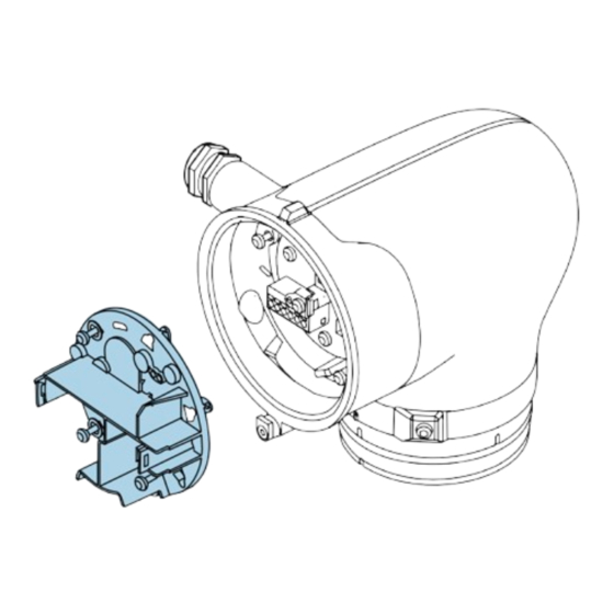
Removing the transmitter housing, replacing the ISEM ribbon cable, electronics module 1 → 1,5 Nm 3 mm (1.1 lbf ft) ‣ Loosen the screw and open the cover. 2 → ‣ Press the tab and remove the display module. Endress+Hauser... - Page 9 Keep the old retaining element partition wall. for the Ex-de partition wall until the repair work is completed. 7 → ‣ Carefully pull the electronics module halfway out of the transmitter housing. On the bottom of the electronics module, disconnect the plug. Endress+Hauser...
- Page 10 9 → ‣ Fit the protection ring for the Ex-de partition wall on the electronics module to prevent damage to the module and set the electronics module aside. 10 → ‣ Disconnect the ribbon cable from the ISEM module. Endress+Hauser...
-
Page 11: Preparatory Steps
Proceed as described in Section 7.1, → 8 and as illustrated in the diagrams below. 1 → 2 → 0,8 Nm (0.6 lbf ft) ‣ ‣ Loosen the Torx screws on the Remove the ISEM module from ISEM module. the interface. Endress+Hauser... -
Page 12: Promass 10
Proceed as described in Section 7.1, → 8 and as illustrated in the diagrams below. 1 → 2 → 0,8 Nm (0.6 lbf ft) ‣ ‣ Loosen the Torx screws on the Remove the ISEM module from ISEM module. the interface. Endress+Hauser... -
Page 13: Reassembly
‣ ‣ Insert the new S+T-DAT into the Align and position the ISEM electronics module in the sensor interface in ISEM electronics module. Pay accordance with the diagram. Pay attention to pin diagram! attention to pin diagram! Endress+Hauser... - Page 14 2 → ‣ ‣ Insert the new S+T-DAT into the Align and position the ISEM electronics module in the sensor interface in ISEM module. Pay attention to accordance with the diagram. Pay attention to pin diagram! pin diagram! Endress+Hauser...
- Page 15 Reassemble the transmitter as described in Section 7.6, → 15. 10.3 Reassembling the transmitter housing 1 → 2 → ‣ ‣ Fit the transmitter and turn it. Turn the transmitter until the thread is at the end stop. Endress+Hauser...
- Page 16 Tighten the screws on the front. transmitter, tighten the twist protection. 5 → ‣ Insert the ribbon cable. Pay attention to the plug coding! 6 → ‣ Push the electronics module with the protection ring into the transmitter housing. Endress+Hauser...
- Page 17 (end stop). The ribbon cable may not be damaged or squeezed! 9 → ‣ When the electronics module is installed, the protection ring is automatically pushed towards the front. The ring can be disposed of following the installation of the electronics module. Endress+Hauser...
- Page 18 Unscrew the Torx screws of the retaining element as far as the edges of the guide elements (A in the graphic), while making sure you continue to apply pressure to hold the retaining element in place. This releases the fastening elements (see Figure 13 below, item nos. 1-3 ). Endress+Hauser...
- Page 19 Affix the Exi adhesive label supplied (see graphic 15 below) and the connection sign (see graphic 16 below) at the same position on the new electronics module. 15 → Ex i ‣ Affixing the Exi adhesive label on the new electronics module. Endress+Hauser...
- Page 20 Affixing the connection sign on the new electronics module. 17 → ‣ Push the ribbon cable into the holder, plug in the plug, fit the display module. 18 → ‣ Fit the display module, making sure it engages with a click. Endress+Hauser...
-
Page 21: Final Steps
SmartBlue App must be re-established. Restoring the S+T-DAT backup In the SmartBlue App: open system. Open device management. Open reset device. Restore S-DAT backup. Open device management. Open reset device. Restore T-DAT backup. Totalizer ‣ Reset the totalizer. Endress+Hauser... -
Page 22: Disposal
(WEEE), the product is marked with the depicted symbol in order to minimize the disposal of WEEE as unsorted municipal waste. Do not dispose of products bearing this marking as unsorted municipal waste. Instead, return them to Endress+Hauser for disposal under the applicable conditions. - Page 23 Entsorgung ..............42 Endress+Hauser...
-
Page 24: Übersicht Ersatzteilset
Produktionsnummer (auf dem Aufkleber direkt auf dem Ersatzteil) unterscheiden! • Durch Eingabe der Produktionsnummer des Ersatzteiles im Ersatzteilfindetool kann die Bestellnummer des entsprechenden Ersatzteilsets ermittelt werden. • Wir empfehlen Einbauanleitung und Verpackung immer zusammen aufzubewahren. Endress+Hauser... -
Page 25: Bestimmungsgemäße Verwendung
Mit Zulassung (z.B. IECEx) 2, 3 Bei eichfähigem Verkehr 1 = Ausgebildete Fachkraft des Kunden, 2 = Von Endress+Hauser autorisierter Servicetechniker, 3 = Endress+Hauser (Messgerät an Hersteller zurücksenden) 4 = Mit der lokalen Zulassungsstelle prüfen, ob ein Ein-/Umbau unter Aufsicht erfolgen muss. -
Page 26: Sicherheitshinweise
• Änderungen am Messgerät sind nicht zulässig. • Gehäuse nur kurzzeitig öffnen. Eindringen von Fremdkörpern, Feuchtigkeit oder Verunreinigung vermeiden. • Defekte Dichtungen nur durch Original-Dichtungen von Endress+Hauser ersetzen. • Defekte Gewinde erfordern eine Instandsetzung des Messgeräts. • Gewinde (z.B. von Elektronikraum- und Anschlussraumdeckel) müssen geschmiert sein, sofern keine abriebfeste Trockenschmierung vorhanden ist. -
Page 27: Verwendete Symbole
(z.B. Hochspannungstest gemäß Herstellerangaben). • Servicestecker: • Nicht in explosionsfähiger Atmosphäre anschließen. • Nur an Servicegeräte von Endress+Hauser anschließen. • Die in der Betriebsanleitung aufgeführten Hinweise zum Transport und zur Rücksendung beachten. Bei Fragen kontaktieren Sie bitte Ihre zuständige Endress+Hauser Serviceorganisation. -
Page 28: Werkzeugliste
0,5 x 3,5 mm 3 mm T10, T20 Proline 10 Messumformergehäuse Aluminium Ex de Ausbau Messumformergehäuse, Austausch ISEM-Flachbandkabel, Elektronikmodul 1 → 1,5 Nm 3 mm (1.1 lbf ft) ‣ Schraube lösen und Deckel öffnen. 2 → ‣ Lasche drücken und Anzeigemodul wegnehmen. Endress+Hauser... - Page 29 Torx Schrauben lösen und Sicherungselement für die Ex-de- Trennwand Altes Sicherungselement für die wegnehmen. Ex-de-Trennwand bis zum Abschluss der Reparatur aufbewahren. 7 → ‣ Elektronikmodul vorsichtig bis zur Hälfte aus dem Messumformergehäuse herausziehen. An der Unterseite des Elektronikmoduls den Stecker abziehen. Endress+Hauser...
- Page 30 EA01344D 8 → ‣ Elektronikmodul aus Messumformergehäuse herausnehmen. 9 → ‣ Den Schutzring für die Ex-de-Trennwand auf das Elektronikmodul aufziehen, um Beschädigungen am Modul zu vermeiden und Elektronikmodul ablegen. 10 → ‣ Flachbandkabel vom ISEM-Modul abziehen. Endress+Hauser...
-
Page 31: Promag 10
Austausch ISEM- Modul, S+T-DAT ‣ Vorgehen wie in Kap. 7.1, → 28 und wie in den Bildern unten. 1 → 2 → 0,8 Nm (0.6 lbf ft) ‣ ‣ Torx Schrauben vom ISEM-Modul ISEM-Modul aus Schnittstelle lösen. herausnehmen. Endress+Hauser... -
Page 32: Promass 10
Nach Austausch S+T-DAT den notierten Wert wieder in das Gerät eingegeben. Austausch ISEM-Modul, S+T-DAT ‣ Vorgehen wie in Kap. 7.1, → 28 und wie in den Bildern unten. 1 → 2 → 0,8 Nm (0.6 lbf ft) ‣ ‣ Torx Schrauben vom ISEM-Modul ISEM-Modul aus Schnittstelle lösen. herausnehmen. Endress+Hauser... -
Page 33: Zusammenbau
Pins nicht beschädigt oder verbogen werden! Zusammenbau 10.1 Hinweis zum Zusammenbau Messumformergehäuse Promag 1 → 2 → ‣ ‣ Neues S+T-DAT in ISEM-Elektronikmodul gemäss Abbildung in Sensorschnittstelle ausrichten ISEM-Elektronikmodul und platzieren. Pinbild beachten! einstecken. Pinbild beachten! Endress+Hauser... - Page 34 Messumformer zusammenbauen wie in Kap. 7.6, → 35 beschrieben. 10.2 Hinweis zum Zusammenbau Messumformergehäuse Promass 1 → 2 → ‣ ‣ Neues S+T-DAT in ISEM-Modul ISEM-Elektronikmodul gemäss Abbildung in Sensorschnittstelle ausrichten einstecken. Pinbild beachten! und platzieren. Pinbild beachten! Endress+Hauser...
- Page 35 Schrauben gemäss Drehmoment anziehen. Folgendes ist zu beachten: ‣ Messumformer zusammenbauen wie in Kap. 7.6, → 35 beschrieben. 10.3 Zusammenbau Messumformergehäuse 1 → 2 → ‣ ‣ Messumformer aufsetzen und Messumformer drehen bis zum drehen. Anschlag vom Gewinde. Endress+Hauser...
- Page 36 ‣ ‣ Messumformer 1/4 - 1/2 Umdrehung zurück drehen bis vorne auf die Die Schrauben am Markierung. Messumformer anziehen, die Verdrehsicherung anziehen. 5 → ‣ Flachbandkabel einstecken. Steckercodierungbeachten! 6 → ‣ Elektronikmodul mit Schutzring in das Messumformergehäuse hineinschieben. Endress+Hauser...
- Page 37 Elektronikmodul bis zum Anschlag vorsichtig in das Messumformergehäuse hineinschieben. Das Flachbandkabel darf nicht beschädigt oder gequetscht werden! 9 → ‣ Der Schutzring wird beim Einbau des Elektronikmoduls automatisch nach vorne geschoben. Dieser kann nach Montage des Elektronikmoduls entsorgt werden. Endress+Hauser...
- Page 38 Messumformergehäuse angezogen ist! ‣ Torx Schrauben des Sicherungselements bis an die Kanten der Führungselemente (A in der Grafik) herausdrehen. Dabei das Sicherungselement unter stetigem Druck festhalten. Dadurch werden die Halteelemente (siehe Bild 13 unten, Pos. No. 1-3 ) freigegeben. Endress+Hauser...
- Page 39 Option M ‣ Modbus RS485, 4-20mA ‣ Den mitgelieferten Exi-Aufkleber (siehe Grafik 15 unten) und das Anschlussschild (siehe Grafik 16 unten) auf dem neuen Elektronikmodul an gleicher Stelle anbringen. 15 → Ex i ‣ Anbringen Exi-Aufkleber auf neuem Elektronikmodul. Endress+Hauser...
- Page 40 EA01344D 16 → Output 1 Output 1 ‣ Anbringen Anschlussschild auf neuem Elektronikmodul. 17 → ‣ Flachbandkabel in Halterung schieben, Stecker einstecken, Anzeigemodul anbringen. 18 → ‣ Anzeigemodul aufsetzen bis es einrastet. Endress+Hauser...
-
Page 41: Abschliessende Arbeiten
Nach Ausführung der unten genannten Schritte, erfolgt ein Geräte Neustart. Die Verbindung via SmartBlue App muss wieder hergestellt werden. S+T-DAT Sicherung wiederherstellen In der SmartBlue App: System öffnen. Geräteverwaltung öffnen. Gerät zurücksetzen öffnen. S-DAT-Sicherung wiederherstellen. Geräteverwaltung öffnen. Gerät zurücksetzen öffnen. T-DAT-Sicherung wiederherstellen. Totalizer ‣ Totalizer wieder einstellen. Endress+Hauser... -
Page 42: Entsorgung
Gemäß der Richtlinie 2012/19/EU über Elektro- und Elektronik-Altgeräte (WEEE) ist das Produkt mit dem abgebildeten Symbol gekennzeichnet, um die Entsorgung von WEEE als unsortierten Hausmüll zu minimieren. Gekennzeichnete Produkte nicht als unsortierter Hausmüll entsorgen, sondern zu den gültigen Bedingungen an Endress+Hauser zurückgeben. Endress+Hauser... - Page 44 *71519413* 71519413 www.addresses.endress.com...
Need help?
Do you have a question about the XPD0064 Series and is the answer not in the manual?
Questions and answers