Table of Contents

Related Manuals for Seg DiggiMEC


Summary of Contents for Seg DiggiMEC
- Page 1 PROTECTION MADE SIMPLE. WI Line DiggiMEC NANO-HMI WITH FLAG INDICATORS / OUTPUT RELAYS RESET R E S E T NANO-HMI WITH FLAG INDICATORS / OUTPUT RELAYS Version: 1.0 Original document English MANUAL DIGGIMEC-1.0-EN-MAN Build 56555 Revision B...
- Page 2 E-mail: support@SEGelectronics.de SEG Electronics GmbH reserves the right to update any portion of this publication at any time. Information provided by SEG Electronics GmbH is believed to be correct and reliable. However, no responsibility is assumed by SEG Electronics GmbH unless otherwise expressly undertaken.
-
Page 3: Table Of Contents
............6█ DiggiMEC – Nano HMI with Flag Indicators and Output Relays ..... . . -
Page 4: Safety Messages And Proper Use Of The Diggimec
1 Safety Messages and Proper Use of the DiggiMEC 1.1 Important Definitions Safety Messages and Proper Use of the DiggiMEC Important Definitions The types of messages shown below serve the safety of life and limb as well as for the appropriate operating life of the device. -
Page 5: Proper Use Of The Device And Of This Manual
Only the trip-coil output “TC+/−” of the WIC1 may be used for tripping a breaker. The bistable output relays of a DiggiMEC, that is connected to the WIC1, may be used only for visualization purposes. It is not permitted to use these relay contacts for any... -
Page 6: Important Information
1 Safety Messages and Proper Use of the DiggiMEC 1.3 Important Information Important Information Out-of-Date Documentation? This publication may have been revised or updated since this copy was produced. To verify that you have the latest revision, please visit the download section of our website: •... -
Page 7: Diggimec - Nano Hmi With Flag Indicators And Output Relays
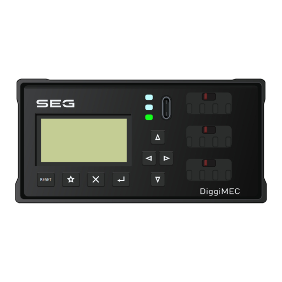
DiggiMEC – Nano HMI with Flag Indicators and Output Relays The DiggiMEC is a remote HMI to be used in connection with a WIC1 (version 2) protection relay. (It cannot be used with the predecessor WIC1.) An overview of the elements and connectors can be found here: ╚═▷... - Page 8 A defective cable might impair the internal voltage of the WIC1 and DiggiMEC, and this might affect the capability of the device to operate a trip coil and outputs.
-
Page 9: Order Form Of The Diggimec
2 DiggiMEC – Nano HMI with Flag Indicators and Output Relays 2.1 Order Form of the DiggiMEC Order Form of the DiggiMEC Nano-HMI with Flag Indicators DiggiMEC Type ↓ Door mounting, 1 bi-stable relay / flag indicator Door mounting, 3 bi-stable relays / flag indicators DIGGIMEC-1.0-EN-MAN... -
Page 10: Diggimec Dimension Drawings
3 DiggiMEC Dimension Drawings DiggiMEC Dimension Drawings 102.0 [4.02] 96.0 [3.78] [2.09] [1.89] RESET Fig. 2: DiggiMEC, front view. All dimensions in mm, except dimensions in brackets [inch]. 55.8 [2.20] 49.8 [1.96] [1.89] [2.09] [0.98] 24.8 [1.22] [0.98] Fig. 3: DiggiMEC, side view. - Page 11 Installation Diagram – Cutout for Door Mounting of the DiggiMEC [3.62] Fig. 4: Door Cut-out. All dimensions in mm, except dimensions in brackets [inch]. The DiggiMEC can be mounted into a standard door cutout, that is already available by default with most cabinets. The rear side (╚═▷ “4.1 DiggiMEC Connectors”) features an RJ45 plug: It may only be used...
-
Page 12: Hardware
Rear Side Option: RJ45 Hardware Variant DiggiMEC-A D - 47906 Kempen Front View Torque: 0.5 Nm System not connected (4.4 lb⋅in) LED2 LED3 Fig. 5: DiggiMEC‑A: Position of flag indicators and LEDs, and connectors at the rear side. DiggiMEC DIGGIMEC-1.0-EN-MAN... - Page 13 D - 47906 Kempen Front View Torque: 0.5 Nm System (4.4 lb⋅in) LED2 LED3 Fig. 6: DiggiMEC‑B: Position of flag indicators and LEDs, and connectors at the rear side. Slot Max. Screw type Description Torques of the Screws 0.5 Nm M3 slotted Connections for functional earth and relay outputs (4.4 lb⋅in)
- Page 14 Only the trip-coil output “TC+/−” of the WIC1 may be used for tripping a breaker. The bistable output relays of a DiggiMEC, that is connected to the WIC1, may be used only for visualization purposes. It is not permitted to use these relay contacts for any...
- Page 15 WIC1 would not be able to detect this. This makes the whole protection concept unsafe and not permissible. • The WIC1 Backup Protection cannot switch a DiggiMEC output relay. It only uses the •...
-
Page 16: Flag Indicator / Output Relays Settings (Diggimec)
Each of these flag indicators is mechanically coupled with a bistable output relay. At any time, the DiggiMEC can toggle the state of an FIx. Note that each FIx is always only set with the rising edge of the assigned signal. - Page 17 All output relay contacts are potential-free. Each relay can be assigned a signal out of the »assignment list«. NOTICE! Whenever the DiggiMEC is not actively used by a human operator we recommend to keep the lid closed. (Depending on the local security directives you might also want to use the sealing option.) This prevents an unintended re-positioning of the flag indicators / output relays.
-
Page 18: Navigation - Operation
(3) The flag indicator BO3 has a “Form C” (changeover) contact. • The device variant DiggiMEC‑A has only one bistable output relay BO2. • • The device variant DiggiMEC‑B has three bistable output relays BO1, BO2, BO3. • See also ╚═▷... - Page 19 This allows for quickly browsing through a long list. (7) »Reset« Key A key-press resets latched signals (including latched LEDs, flag indicators and the Fault Display screen). See the WIC1 User Manual (chapter “Reset”) for details. DIGGIMEC-1.0-EN-MAN DiggiMEC...
- Page 20 Connection to the PC software Smart view can be done via this USB-C interface. Moreover, this is a sufficient power supply for DiggiMEC and WIC1, in case the WIC1 is not supplied via the CTs or any auxiliary power (WIC1‑4 only).
-
Page 21: Special Keys During Power-On
Some keys have a special functionality when being pressed during the power-on / boot process. • »↵« during power-on – After a confirmation dialog, the DiggiMEC enters a special • “Service Mode”. This operating mode allows for installing a new firmware on the DiggiMEC. -
Page 22: Menu Structure
• Device planning This will usually be your first step during commissioning: Device planning • Within sub-menu WIC1 + DiggiMEC, you can specify • fundamental properties of your device setup. In particular, you can define for a WIC1‑2 (with DIP switches) or WIC1‑3 (with HEX switches) whether the... - Page 23 • Force a WIC1 restart. • • Force a trip command. • • Force a reset of all settings to their factory defaults. • • Force a temporary transition of the WIC1 into the • backup protection mode (for testing purposes). DIGGIMEC-1.0-EN-MAN DiggiMEC...
-
Page 24: Parameter Changes - "Ok" Key
NOTICE! Make sure that WIC1 and DiggiMEC are sufficiently supplied, especially when both are supplied by the CTs. A sag of the supply might result in losing all parameter changes that have not been transferred to the WIC1 yet. - Page 25 5 Navigation – Operation 5.4 Parameter Changes – “OK” key You are asked for the password. Enter Password On the DiggiMEC panel, the password is Password: entered the same way as any numerical setting value, i. e. via navigation keys »◀«, »▶...
- Page 26 “?” character that appears instead of the “*” in the heading line. In this case the protection device refuses to activate the new value(s), and you are expected to re-edit the values that are marked by the “?”. DiggiMEC DIGGIMEC-1.0-EN-MAN...
-
Page 27: Operation Via Smart View
Device not connected Fig. 8: Connect the PC to the DiggiMEC and the DiggiMEC to the WIC1, and within Smart view, specify the connection settings. Apart from plugging in the required cables, there are essentially two steps to be done for establishing a connection: •... - Page 28 Smart view should now retrieve the complete menu tree, including all setting values and run-time data. After that, you should see a menu tree with the same top-level categories as on the DiggiMEC panel. NOTICE! If Smart view complains about a missing “device model” then your Smart view installation is probably older than the WIC1 firmware.
-
Page 29: Technical Data - Diggimec
Conductor size ≤ AWG 14 [2.5 mm²]. NOTICE! Use an Ethernet cable CAT 3 (or better) with shielding for the connection between WIC1 and DiggiMEC. Crossover cables must not be used! Climatic and Environmental Data Storage Temperature: −30°C to +80°C (−22°F to 176°F) Operating Temperature: −20°C to +60°C (−4°F to 140°F) -
Page 30: Degree Of Protection En 60529
6.3 Degree of Protection EN 60529 Door cutout (Height / Width): 45 mm / 92 mm Material, Housing: Plastic Weight: • DiggiMEC‑A (without packaging): approx. 160 g • • DiggiMEC‑A (incl. packaging): approx. 300 g • • DiggiMEC‑B (without packaging): approx. 190 g •... -
Page 31: Binary Output Relays
6 Technical Data – DiggiMEC 6.5 Binary Output Relays Binary Output Relays Continuous current, max. 1 A AC switching current: Max. switching voltage: 250 VAC Contact type: 1 or 3 bistable relays, depending on device type: • DiggiMEC‑A: • 1 normally open (Form A) contact •... -
Page 32: Appendix
6(a)‑I, 6(c), 7(a), 7(c)‑I) 2015/863/EU (2015-03-31, amending Annex II to Directive 2011/65/EU of the Eurpoean Parliament and of the council as regards the list of restricted substances) Product standards IEC 60255-1, 2009 IEC 60255-26, 2013 IEC 60255-27, 2013 DiggiMEC DIGGIMEC-1.0-EN-MAN... - Page 33 MANUAL docs.SEGelectronics.de/DiggiMEC SEG Electronics GmbH reserves the right to update any portion of this publication at any time. Information provided by SEG Electronics GmbH is believed to be correct and reliable. However, SEG Electronics GmbH assumes no responsibility unless otherwise expressly undertaken.
Need help?
Do you have a question about the DiggiMEC and is the answer not in the manual?
Questions and answers