Samson 4763 Mounting And Operating Instruction
Hide thumbs
Also See for 4763:
- Mounting and operating instructions (56 pages) ,
- Mounting and operating instructions (28 pages) ,
- Mounting and operating instructions (28 pages)

Related Manuals for Samson 4763


Summary of Contents for Samson 4763
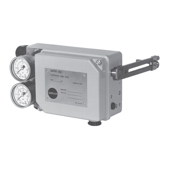
- Page 1 EB 8359-2 EN Translation of original instructions Type 4763 Electropneumatic Positioner Edition January 2022...
- Page 2 Note on these mounting and operating instructions These mounting and operating instructions assist you in mounting and operating the device safely. The instructions are binding for handling SAMSON devices. The images shown in these instructions are for illustration purposes only. The actual product may vary.
-
Page 3: Table Of Contents
Contents Safety instructions and measures ..............1-1 Notes on possible severe personal injury ............1-3 Notes on possible personal injury ..............1-3 Notes on possible property damage .............1-4 Special instructions concerning explosion protection ........1-5 Markings on the device ................2-1 Nameplate ....................2-1 Article code ....................2-2 Design and principle of operation ...............3-1 Technical data ....................3-3 Summary of explosion protection approvals ..........3-4... - Page 4 Converting the electropneumatic into a pneumatic positioner ......9-2 Periodic inspection and testing of the positioner ..........9-2 Decommissioning ..................10-1 Removal ....................11-1 Repairs ....................12-1 12.1 Servicing explosion-protected devices ............12-1 12.2 Returning devices to SAMSON ..............12-1 Disposal ....................13-1 Certificates ....................14-1 Annex......................15-1 15.1 Accessories ....................15-1 15.2 After-sales service ..................15-2...
-
Page 5: Safety Instructions And Measures
In case operators intend to use the positioner in applications or conditions other than those specified, contact SAMSON. SAMSON does not assume any liability for damage resulting from the failure to use the de- vice for its intended purpose or for damage caused by external forces or any other external factors. - Page 6 Î Check with the plant operator for details on further protective equipment. Revisions and other modifications Revisions, conversions or other modifications of the product are not authorized by SAMSON. They are performed at the user's own risk and may lead to safety hazards, for example. Fur- thermore, the product may no longer meet the requirements for its intended use.
-
Page 7: Notes On Possible Severe Personal Injury
Safety instructions and measures − Type 4763-0: 2014/30/EU, 2011/65/EU − Type 4763-1/-8: 2014/30/EU, 2014/34/EU, 2011/65/EU Devices with an EAC marking fulfill the requirements of the Regulation TR CU 020/2011. See the 'Certificates' section for the declarations of conformity and EAC certificates. Referenced documentation The following documents apply in addition to these mounting and operating instructions: −... -
Page 8: Notes On Possible Property Damage
Safety instructions and measures Incorrect electrical connection will render the explosion protection unsafe. Î Adhere to the terminal assignment. Î Do not undo the enameled screws in or on the housing. Intrinsic safety rendered ineffective in intrinsically safe devices. Every time the positioner is operated, even not within the plant (e.g. during maintenance, calibration and work on equipment), it must be ensured that the conditions for intrinsical- ly safe circuits are observed. -
Page 9: Special Instructions Concerning Explosion Protection
Safety instructions and measures 1.4 Special instructions concerning explosion protection Equipment for use in zone 2/zone 22 Î In equipment operated according to type of protection Ex nA II (non-sparking equip- ment) according to EN 60079-15: 2003, circuits may be connected, interrupted or switched while energized only during installation, maintenance or repair. Î... - Page 10 EB 8359-2 EN...
-
Page 11: Markings On The Device
Positioner single-acting Supply Input See technical data for ambient temperature Var.-ID Serial no. Model Date SAMSON AG D-60314 Frankfurt Made in Germany 4763 i/p Positioner single-acting Input Supply max. * See technical data and explosion-protection certificate for permissible ambient temperature... -
Page 12: Article Code
Markings on the device 2.2 Article code Electropneumatic Positioner Type 4763- x 1 x 0 0 x x x x 0 x 0 x x 0 Explosion protection Without ATEX: II 2G Ex ia IIC T6 Gb CCC Ex: Ex ia IIC T4 ~ T6 Gb... - Page 13 Markings on the device Electropneumatic Positioner Type 4763- x 1 x 0 0 x x x x 0 x 0 x x 0 Temperature range Standard Low temperature down to –45 °C Special version Without 0 0 0 EAC explosion protection certification...
- Page 14 Markings on the device Type 4763 up to device index .04 Pneumatic connections ISO 228/1 G ¼ ¼-18 NPT ISO-7/1-Rc ¼ Electrical connection (cable gland) ISO 228/1 G ½ M20x1.5 blue (plastic) M20x1.5 black (plastic) Harting connector HAN 7D M20x1.5 blue (metal) M20x1.5 (metal) i/p converter Type 6109 Type 6112 Set point 4 to 20 mA...
-
Page 15: Design And Principle Of Operation
Design and principle of operation 3 Design and principle of oper- The adjustable volume restriction Q (14) and Xp (gain) restriction (13) are used to opti- ation mize the control loop of the positioner. The electropneumatic positioner is used to The range spring (6), which can be ex- assign the valve position (controlled variable) changed, is assigned to both the rated valve... - Page 16 Design and principle of operation 5 6.1 13 10.2 7 Fig. 3-1: Positioner with cover removed 2 2.1 Travel 10.2 10.1 Output 10.2 10.1 Supply Arrangement of nozzle/flapper plate for in- creasing/decreasing <> operating direction Fig. 3-2: Functional diagram EB 8359-2 EN...
-
Page 17: Technical Data
Design and principle of operation 3.1 Technical data Controlled variable (travel range) 7.5 to 60 mm, with lever extension: 7.5 to 90 mm Set point 4 to 20 mA (Ex), = 250 Ω 1) 4 to 20 mA (without explosion protection), R = 200 Ω Split-range 0 to 50 % or 50 to 0 to 20 mA, = 200 Ω... -
Page 18: Summary Of Explosion Protection Approvals
2015-10-12 Class I, Div. 2, Groups A, B, C, D; Class II, Div. 2 Groups F, G; Class III Number PTB 03 ATEX 2183 X 4763-8 ATEX II 3G Ex nA ic IIC T6 Gc Date 2003-09-30 EB 8359-2 EN... -
Page 19: Dimensions In Mm
Design and principle of operation 3.3 Dimensions in mm Useable lever length I: 40 to 127 mm (with lever extension 40 to 200 mm) Pneumatic connections: ISO-228/1-G ¼ Cable gland: Device index .02 and lower: Pg 13.5 Device index .03 and higher: M20x1.5 connection for housing with G thread... - Page 20 EB 8359-2 EN...
-
Page 21: Shipment And On-Site Transport
Î Observe the storage instructions. Î Avoid long storage times. 4.2 Removing the packaging Î Contact SAMSON in case of different from the positioner storage conditions. Observe the following sequence: Note Î Do not remove the packaging and the... - Page 22 Shipment and on-site transport − Do not damage the corrosion protection (coating). − Protect the positioner against moisture and dirt. In damp spaces, prevent con- densation. If necessary, use a drying agent or heating. − Make sure that the ambient air is free of acids or other corrosive media.
-
Page 23: Installation
Installation 5 Installation NOTICE The work described in this section is only to Risk of malfunction due to incorrect mount- be performed by personnel appropriately ing parts/accessories. qualified to carry out such tasks. Î Only use the mounting parts and acces- sories listed in these mounting and oper- ating instructions to mount and install the DANGER... -
Page 24: Preparation For Installation
Installation 5.2 Preparation for installation Operating direction increasing/decreasing <> Before mounting, make sure the following − The signal pressure p decreases as the conditions are met: input signal p (set point) rises − The positioner is not damaged. − The signal pressure p rises as the input −... - Page 25 Installation Range spring Cover plate Nozzle block Feeler pin Marking Flapper plate Operating direction << Operating direction <> Flapper plate below the feeler pin Flapper plate on top of feeler pin Fig. 5-1: Position of nozzle block, cover plate removed Actuator stem extends (FA) p st p st Lever (1) located at top of plate (20)
-
Page 26: Positioner Attachment
Installation 5.3 Positioner attachment Î Place both the support (28) and the clamping plate (26) on the rod (27) and lightly fasten. Move the support until both 5.3.1 Attachment to valve the center of the plate (20) and the sup- with cast yoke port (28) are aligned when the valve is at half of the valve travel. - Page 27 Installation Lever 2.1 Nut Fastening screw Plate Screw Stem connector Plug stem Travel indicator Clamping plate Rod (pillar) Support 22 23 Fig. 5-6: Attachment to valves with cast yokes (NAMUR rib) 20 2.1 Fig. 5-7: Attachment to valves with rod-type yokes EB 8359-2 EN...
-
Page 28: Pressure Gauges
Installation For tight-closing valves, the maximum signal NOTICE pressure pst is roughly estimated as fol- Risk of malfunction due to failure to comply lows: with air quality requirements. d² · π · ∆p Î Only use supply air that is dry and free = F + [bar] 4 ·... - Page 29 Installation Table 5-1: Range springs Rated travel Min./max. travel [mm] Set point (input signal) Range spring [mm] Standard travels for SAMSON valves with lever l (40 to 127 mm in length) 100 % 7.5 to 15 50 % 100 % 14 to 32 50 % 30 to 70 100 %...
- Page 30 Installation With a set point, for example 4 to 20 mA, Î Exchange range spring. Slide lever with the valve must move through its entire travel shaft through sleeve (3), positioner hous- range from 0 to 100 %. The starting point ing and bracket (6.1). then is 4 mA and the upper range value Î...
-
Page 31: Adjusting The Positioner
Installation 5.6 Adjusting the positioner 5.6.1 Air output capacity and proportional band X WARNING Fig. 5-9 Intrinsic safety rendered ineffective in 1. Close the volume restriction (14) as far intrinsically safe devices. as the required positioning speed per- Î Only connect intrinsically safe devices in- mits. -
Page 32: Zero And Span
Installation Î With operating direction increasing/in- 180° creasing <<: adjust starting point to 270° 90° 4.5 mA (slightly raised). 0° Zul. Supply Alim. Î With operating direction increasing/de- creasing <>: adjust starting point to 6 bar 3 bar 1,4 bar 19.5 mA (slightly lowered). Starting point (zero) e.g. -
Page 33: Electrical Connection
Installation b) Actuator with “actuator stem Upper range value (span), e.g. 4 mA retracts” (FE) fail-safe action 3. Once the starting point has been set, in- crease the input signal to 4 mA at the When using an actuator with fail-safe action ammeter. - Page 34 Installation used with plugs. Fit equipment used in ambi- WARNING ent temperatures below –20 °C with metal Intrinsic safety rendered ineffective in cable glands. intrinsically safe devices. Equipment for use in zone 2/zone 22: Î Only connect intrinsically safe devices in- tended for use in intrinsically safe circuits In equipment operated according to type of to certified intrinsically safe input-con- protection Ex nA II (non-sparking equipment)
-
Page 35: Accessories And Mounting Parts
Installation Input control signal 0/4 to 20 mA Fig. 5-11: Electrical connection 5.8 Accessories and mounting parts Accessories – Mounting parts Ordering number Range spring 1 1190-0736 Range spring 2 1190-0737 Range spring 3 1190-0738 Lever I 1690-6469 Lever extension 1400-6716 Pressure gauge attachment 1402-1637 Pressure gauge attachment (copper-free) 1402-1638... - Page 36 5-14 EB 8359-2 EN...
-
Page 37: Start-Up
Start-up 6 Start-up Before start-up, make sure the following con- ditions are met: The work described in this section is only to − The positioner is properly mounted ac- be performed by personnel appropriately cording to the instructions. qualified to carry out such tasks. −... - Page 38 EB 8359-2 EN...
-
Page 39: Operation
Operation 7 Operation The positioner is ready for use after it has been mounted and the pneumatic and elec- tric connections have been established (see the 'Installation' section). WARNING Crush hazard arising from moving parts on the valve. Î Do not touch any moving valve parts while the control valve is in operation. - Page 40 EB 8359-2 EN...
-
Page 41: Malfunction
Risk of fatal injury due to the ignition of an Note explosive atmosphere. Contact SAMSON's After-sales Service for Î Installation, operation or maintenance of malfunctions not listed in the table. the positioner must only be performed by personnel who has undergone special 8.2 Emergency action... - Page 42 Malfunction Table 8-1: Troubleshooting Description of fault Measures Actuator moves too slowly. Î Check the supply pressure. Î Check the cross-section of the piping and screw fittings. Î Check the configuration of the mounting parts. Actuator moves in the wrong direction. Î...
-
Page 43: Servicing
The positioner was checked by SAMSON before it left the factory. WARNING − The product warranty becomes void if Intrinsic safety rendered ineffective in in- service or repair work not described in trinsically safe devices. -
Page 44: Changing The Operating Direction Of The Positioner Control Loop
Servicing 9.1 Changing the operating di- Note rection of the positioner For details on the converted Type 4765 Posi- control loop tioner refer to Mounting and Operating In- structions EB 8359-1. To change the operating direction of the po- sitioner control loop (increasing/increasing, Table 9-1: Conversion kits increasing/decreasing): Î... - Page 45 Servicing Screw fitting Hose Printed circuit board Connecting plate i/p converter Sealing element Connecting nipple Fig. 9-1: Converting the positioner Table 9-2: Recommended inspection and testing Inspection and testing Action to be taken in the event of a negative result Check the markings, labels and nameplates on Immediately renew damaged, missing or incor- the positioner for their readability and complete- rect nameplates or labels.
- Page 46 EB 8359-2 EN...
-
Page 47: Decommissioning
Decommissioning 10 Decommissioning The work described in this section is only to be performed by personnel appropriately qualified to carry out such tasks. DANGER Risk of fatal injury due to ineffective explo- sion protection. The explosion protection becomes ineffective when the positioner cover is opened. Î... - Page 48 10-2 EB 8359-2 EN...
-
Page 49: Removal
Removal 11 Removal The work described in this section is only to be performed by personnel appropriately qualified to carry out such tasks. DANGER Risk of fatal injury due to the ignition of an explosive atmosphere. Î The following regulations apply to instal- lation in hazardous areas: EN 60079-14 (VDE 0165, Part 1). - Page 50 11-2 EB 8359-2 EN...
-
Page 51: Repairs
Î Do not perform any repair work on your 12.2 Returning devices to own. SAMSON Î Contact SAMSON's After-sales Service for service and repair work. Defective devices can be returned to SAMSON for repair. 12.1 Servicing explosion-pro-... - Page 52 12-2 EB 8359-2 EN...
-
Page 53: Disposal
Disposal 13 Disposal We are registered with the German national register for waste electric equipment (stiftung ear) as a producer of electrical and electronic equipment, WEEE reg. no.: DE 62194439 Î Observe local, national and internation- al refuse regulations. Î Do not dispose of components, lubricants and hazardous substances together with your other household waste. - Page 54 13-2 EB 8359-2 EN...
-
Page 55: Certificates
− EU declaration of conformity for Type 4763-1 − EU declaration of conformity for Type 4763-8 − EAC certificate for Type 4763 − ATEX: EC type examination certificate − CSA certificate The certificates shown were up to date at the time of publishing. - Page 56 14-2 EB 8359-2 EN...
- Page 57 EB 8359-2 EN 14-3...
- Page 58 14-4 EB 8359-2 EN...
- Page 59 EB 8359-2 EN 14-5...
- Page 60 14-6 EB 8359-2 EN...
- Page 61 EB 8359-2 EN 14-7...
- Page 62 14-8 EB 8359-2 EN...
- Page 63 EB 8359-2 EN 14-9...
- Page 64 14-10 EB 8359-2 EN...
- Page 65 EB 8359-2 EN 14-11...
- Page 66 14-12 EB 8359-2 EN...
- Page 67 EB 8359-2 EN 14-13...
- Page 68 14-14 EB 8359-2 EN...
- Page 69 EB 8359-2 EN 14-15...
- Page 70 14-16 EB 8359-2 EN...
- Page 71 EB 8359-2 EN 14-17...
- Page 72 14-18 EB 8359-2 EN...
-
Page 73: Annex
Annex 15 Annex 15.1 Accessories Accessories – Mounting parts Ordering number Range spring 1 1190-0736 Range spring 2 1190-0737 Range spring 3 1190-0738 Lever I 1690-6469 Lever extension 1400-6716 Pressure gauge attachment 1402-1637 Pressure gauge attachment (copper-free) 1402-1638 Mounting kit for valves with cast yoke according to NAMUR 1400-5745 Valves with rod-type yoke according to NAMUR for 18 to 35 mm rod 1400-5745 and 1400-5342... -
Page 74: After-Sales Service
E-mail contact You can reach our after-sales service at aftersalesservice@samsongroup.com. Addresses of SAMSON sales sites The addresses of SAMSON AG and sales sites can be found on our website (www.samsongroup.com). Required specifications Please submit the following details: −... - Page 78 EB 8359-2 EN SAMSON AKTIENGESELLSCHAFT Weismüllerstraße 3 · 60314 Frankfurt am Main, Germany Phone: +49 69 4009-0 · Fax: +49 69 4009-1507 samson@samsongroup.com · www.samsongroup.com...
Need help?
Do you have a question about the 4763 and is the answer not in the manual?
Questions and answers