Samson 4763 Mounting And Operating Instructions
Hide thumbs
Also See for 4763:
- Mounting and operating instruction (78 pages) ,
- Mounting and operating instructions (28 pages) ,
- Mounting and operating instructions (28 pages)

Related Manuals for Samson 4763


Summary of Contents for Samson 4763
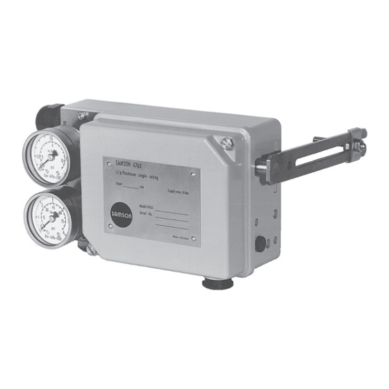
- Page 1 EB 8359-2 EN Translation of original instructions Type 4763 Electropneumatic Positioner Edition April 2020...
- Page 2 Î For the safe and proper use of these instructions, read them carefully and keep them for later reference. Î If you have any questions about these instructions, contact SAMSON‘s After-sales Service (aftersalesservice@samsongroup.com). The mounting and operating instructions for the devices are included in the scope of delivery.
-
Page 3: Table Of Contents
Contents Safety instructions and measures ..............5 Notes on possible severe personal injury ............8 Notes on possible personal injury ..............9 Notes on possible property damage ..............9 Markings on the device ................10 Article code ....................10 Design and principle of operation ..............14 Accessories and mounting parts ..............16 Technical data .....................17 Summary of explosion protection approvals ...........19 Dimensions in mm ..................20... - Page 4 Contents Exchanging the range spring ................33 Converting the electropneumatic into a pneumatic positioner ......34 Servicing.....................36 Preparation for return shipment ..............36 Decommissioning and removal ..............37 Decommissioning ..................37 Removing the positioner ................37 Disposal ......................37 Annex......................38 10.1 After-sales service ..................38 EB 8359-2 EN...
-
Page 5: Safety Instructions And Measures
In case operators intend to use the positioner in other applications or conditions than specified, contact SAMSON. SAMSON does not assume any liability for damage resulting from the failure to use the device for its intended purpose or for damage caused by external forces or any other external factors. - Page 6 Î Check with the plant operator for details on further protective equipment. Revisions and other modifications Revisions, conversions or other modifications of the product are not authorized by SAMSON. They are performed at the user's own risk and may lead to safety hazards, for example.
- Page 7 Safety instructions and measures Servicing explosion-protected devices If a part of the device on which the explosion protection is based needs to be serviced, the device must not be put back into operation until a qualified inspector has assessed it according to explosion protection requirements, has issued an inspection certificate, or given the device a mark of conformity.
-
Page 8: Notes On Possible Severe Personal Injury
Safety instructions and measures 1.1 Notes on possible severe personal injury DANGER Risk of fatal injury due to the formation of an explosive atmosphere. Incorrect installation, operation or maintenance of the positioner in potentially explosive atmospheres may lead to ignition of the atmosphere and ultimately to death. Switching the assignment of the electrical terminals may cause the explosion protection to become ineffective. -
Page 9: Notes On Possible Personal Injury
Safety instructions and measures 1.2 Notes on possible personal injury WARNING Risk of injury by possible movement of the actuator stem after connecting the signal pressure. Î Do not touch or block the actuator stem. 1.3 Notes on possible property damage NOTICE An incorrect electric signal will damage the positioner. -
Page 10: Markings On The Device
Markings on the device 2 Markings on the device 2.1 Article code Electropneumatic Positioner Type 4763- x 1 x 0 0 x x x x 0 x 0 x x 0 Explosion protection Without II 2G Ex ia IIC T6 Gb according to ATEX... - Page 11 The following devices are marked with the article code as listed below: − Type 4763, device index up to .03 − Type 4763, device index .04 (some devices are marked with the new article code) Type 4763 up to device index .04 Explosion protection Without II 2 G Ex ia IIC T6 according to ATEX...
- Page 12 Markings on the device Type 4763 up to device index .04 i/p converters Type 6109 Type 6112 Reference variable 4 to 20 mA 4 to 20 mA 0 to 20 mA 1 to 5 mA EB 8359-2 EN...
- Page 13 EB 8359-2 EN...
-
Page 14: Design And Principle Of Operation
Design and principle of operation 3 Design and principle of oper- The adjustable volume restriction Q (14) and Xp (gain) restriction (13) are used to opti- ation mize the control loop of the positioner. The electropneumatic positioner is used to The range spring (6), which can be ex- assign the valve position (controlled variable) changed, is assigned to both the rated valve... - Page 15 Design and principle of operation 5 6.1 13 10.2 7 Fig. 1: Positioner with cover removed Travel 10.2 10.1 Output 10.2 10.1 Supply Arrangement of nozzle/flapper plate for reverse <> operating direction Fig. 2: Functional diagram EB 8359-2 EN...
-
Page 16: Accessories And Mounting Parts
Design and principle of operation 3.1 Accessories and mounting parts Accessories – Mounting parts Ordering number Range spring 1 1190-0736 Range spring 2 1190-0737 Range spring 3 1190-0738 Lever I 1690-6469 Lever extension 1400-6716 Pressure gauge attachment 1402-0938 Pressure gauge attachment (copper-free) 1402-0939 Mounting kit for valves with cast yoke according to NAMUR 1400-5745... -
Page 17: Technical Data
Design and principle of operation 3.2 Technical data Controlled variable (travel range) 7.5 to 60 mm, with lever extension: 7.5 to 90 mm Reference variable 4 to 20 mA (Ex) = 250 Ω 4 to 20 mA (without explosion protection) = 200 Ω Split-range 0 to 50 % or 0 to 20 mA = 200 Ω... - Page 18 Design and principle of operation With Type 6109 i/p Converter: Permissible ambient temperature –20 to +70 °C –35 to +70 °C (metal cable gland) With Type 6112 i/p Converter: –20 to +80 °C –40 to +80 °C (metal cable gland) –45 to +80 °C (special version) Influences Temperature: <...
-
Page 19: Summary Of Explosion Protection Approvals
3020228 Number Class I,II,III;Div.1, Groups A,B,C,D,E,F,G Class I,Div.2, Groups A,B,C,D; 2015-10-12 Date Class II, Div,2 Groups F,G; Class III PTB 03 ATEX 2183 X Number 4763-8 ATEX II 3G Ex nA ic IIC T6 Gc 2003-09-30 Date EB 8359-2 EN... -
Page 20: Dimensions In Mm
Design and principle of operation 3.4 Dimensions in mm Useable lever length I: 40 to 127 mm (with lever extension 40 to 200 mm) Pneumatic connections: ISO-228/1-G ¼ Cable gland: Device index .02 and lower: Pg 13.5 Device index .03 and higher: M20x1.5 connection for housing with G thread NPT connection... -
Page 21: Measures For Preparation
− Observe the storage instructions. note. − Avoid long storage times. 2. Check the shipment for transportation − Contact SAMSON in case of different damage. Report any transportation storage conditions or long storage periods. damage. Storage instructions 4.1 Unpacking... -
Page 22: Mounting And Start-Up
Mounting and start-up 5 Mounting and start-up 2. Place both the support (28) and the clamping plate (26) on the rod (27) and To attach the positioner to valves with cast lightly fasten. Move the support until both yokes according to IEC 60534-6 (NAMUR the center of the plate (20) and the sup- rib), mounting parts (order no. - Page 23 Mounting and start-up 22 23 Fig. 3: Attachment to valves with cast yokes (NAMUR rib) 20 2.1 Fig. 4: Attachment to valves with rod-type yokes EB 8359-2 EN...
-
Page 24: Pneumatic Connections
Mounting and start-up 5.4 Pneumatic connections The bench range is written on the nameplate either as the bench range or signal pressure range. The operating direction is marked FA WARNING or FE or by a symbol. Risk of injury by possible movement of the Actuator stem extends (FA) actuator stem after connecting the signal Fail-close... -
Page 25: Electrical Connections
Mounting and start-up 5.5 Electrical connections Selecting cables and wires: Observe clause 12 of EN 60079-14: 2008 (VDE 0165, Part 1) for installation of the DANGER intrinsically safe circuits. Clause 12.2.2.7 Risk of fatal injury due to the formation of applies when running multi-core cables and an explosive atmosphere. - Page 26 Mounting and start-up Input control signal 0/4 to 20 mA Fig. 5: Electrical connection EB 8359-2 EN...
-
Page 27: Operating The Positioner
Operating the positioner 6 Operating the positioner When any subsequent changes are made, e.g. reversing the operating direction of the 6.1 Assignment of the posi- positioner control loop or changing the actu- tioner and the actuator ator fail-safe action from “actuator stem ex- tends”... -
Page 28: Determining And Changing The Operating Direction
Operating the positioner 6.1.1 Determining and Make sure the location of the lever (1) and the plate (20), "lever on top of plate" or changing the operating reversed "plate on top of lever" is correct direction (Fig. 6 to Fig. 9). For an increasing input signal (reference variable), the signal pressure p can either be increasing (direct action <<) or decreas-... - Page 29 Operating the positioner Operating direction increasing/increasing Operating direction increasing/decreasing (direct <<) (reverse <>) feeler pin on top of flapper plate flapper plate on top of feeler pin Range spring Cover plate Nozzle block Feeler pin Marking Flapper plate Fig. 10: Position of nozzle block, cover plate removed 100% 100% Open...
-
Page 30: Starting Point And Reference Variable
Operating the positioner 6.2 Starting point and refer- 6.3 Adjustment after mounting ence variable the positioner on the valve Î Connect an ammeter to the control signal The attached lever and the installed range input at the terminals 11 (+) and 12 (–). spring of the positioner are assigned to the values of rated valve travel and the reference Î... - Page 31 Fig. 13: Setting the Xp restriction Table 1: Range springs Rated travel [mm] Min./max. travel [mm] Reference variable (input signal) Range spring Standard travels for SAMSON valves with lever l (40 to 127 mm in length) 100 % 7.5 to 15 50 % 100 % 14 to 32 50 %...
-
Page 32: Setting For Actuator With Fail-Safe Action "Stem Extends
Operating the positioner 6.3.2 Setting for actuator with After correcting the input signal, re-ad- just zero. Then check the upper range fail-safe action “stem value again. extends” Repeat the correction procedure until both To ensure that the total closing force of the values are correct. -
Page 33: Exchanging The Range Spring
Operating the positioner 6.4 Exchanging the range move from its end position earlier; turning it clockwise causes it to move spring from its end position later. If the range is to be altered or changed to Upper range value (span), e.g. 4 mA split-range operation, replace the range 3. -
Page 34: Converting The Electropneumatic Into A Pneumatic Positioner
Converting the electropneumatic into a pneumatic positioner 7 Converting the electropneumatic into a pneumatic positioner The electropneumatic positioner can be con- verted into a Type 4765 Pneumatic Position- er with a conversion kit. Î Required conversion kits: see Table 2 1. Unscrew fastening screws and lift the i/p converter together with the printed circuit board out of the positioner housing. - Page 35 Converting the electropneumatic into a pneumatic positioner Screw fitting Hose Printed circuit board Connecting plate i/p converter Sealing element Connecting nipple Fig. 14: Converting the positioner Table 2: Conversion kits Required conversion kit up to device index .02. For connection with G thread Order no.
-
Page 36: Servicing
SAMSON's after-sales service. − Only use original spare parts by SAMSON, which comply with the original specifications. The Type 4763 Positioner requires no main- tenance. Î Observe the maintenance instructions of any upstream supply air pressure reduc- ing stations. -
Page 37: Decommissioning And Removal
Decommissioning and removal 9 Decommissioning and 9.3 Disposal removal We are registered with the German national register for NOTICE waste electric equipment (stiftung The process is disturbed by interrupting ear) as a producer of electrical and electronic equipment, closed-loop control. WEEE reg. -
Page 38: Annex
You can reach our after-sales service at the following e-mail address. aftersalesservice@samsongroup.com Addresses of SAMSON AG and its subsid- iaries The addresses of SAMSON AG, its subsid- iaries, representatives and service facilities worldwide can be found on our website (www.samsongroup.com) or in all SAMSON product catalogs. - Page 39 EB 8359-2 EN...
- Page 40 EB 8359-2 EN...
- Page 41 EB 8359-2 EN...
- Page 42 EB 8359-2 EN...
- Page 43 EB 8359-2 EN...
- Page 44 EB 8359-2 EN...
- Page 45 EB 8359-2 EN...
- Page 46 EB 8359-2 EN...
- Page 47 EB 8359-2 EN...
- Page 48 EB 8359-2 EN...
- Page 49 EB 8359-2 EN...
- Page 50 EB 8359-2 EN...
- Page 51 EB 8359-2 EN...
- Page 52 EB 8359-2 EN...
- Page 56 EB 8359-2 EN SAMSON AKTIENGESELLSCHAFT Weismüllerstraße 3 · 60314 Frankfurt am Main, Germany Phone: +49 69 4009-0 · Fax: +49 69 4009-1507 samson@samson.de · www.samson.de...
Need help?
Do you have a question about the 4763 and is the answer not in the manual?
Questions and answers