Samson 4765 Mounting And Operating Instructions
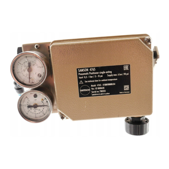
Pneumatic positioner
Hide thumbs
Also See for 4765:
- Mounting and operating instructions (24 pages) ,
- Mounting and operating instructions (25 pages)

Related Manuals for Samson 4765


Summary of Contents for Samson 4765
- Page 1 EB 8359-1 EN Translation of original instructions Type 4765 Pneumatic Positioner Edition March 2020...
- Page 2 Î For the safe and proper use of these instructions, read them carefully and keep them for later reference. Î If you have any questions about these instructions, contact SAMSON‘s After-sales Service (aftersalesservice@samsongroup.com). The mounting and operating instructions for the devices are included in the scope of delivery.
-
Page 3: Table Of Contents
Contents Safety instructions and measures ..............5 Notes on possible property damage ..............7 Markings on the device .................7 Article code ....................7 Design and principle of operation ..............8 Accessories, mounting parts and conversion kits ..........10 Technical data .....................11 Dimensions in mm ..................12 Measures for preparation ................13 Unpacking ....................13 Transporting ....................13... - Page 4 Contents Decommissioning and removal ..............27 Decommissioning ..................27 Removing the positioner ................27 Disposal ......................27 Annex......................28 10.1 After-sales service ..................28 EB 8359-1 EN...
-
Page 5: Safety Instructions And Measures
In case operators intend to use the positioner in other applications or conditions than specified, contact SAMSON. SAMSON does not assume any liability for damage resulting from the failure to use the device for its intended purpose or for damage caused by external forces or any other external factors. - Page 6 Safety instructions and measures Revisions and other modifications Revisions, conversions or other modifications of the product are not authorized by SAMSON. They are performed at the user's own risk and may lead to safety hazards, for example. Fur- thermore, the product may no longer meet the requirements for its intended use.
-
Page 7: Notes On Possible Property Damage
Î Blow through all air pipes and hoses thoroughly before connecting them. 2 Markings on the device 2.1 Article code Pneumatic positioner Type 4765- 0 Spring Spring 1, travel = 15 mm Spring 2, travel = 30 mm, split range 15 mm... -
Page 8: Design And Principle Of Operation
Design and principle of operation 3 Design and principle of oper- Any change in the control signal p or the valve position causes the pressure to change ation upstream or downstream of the booster. The The pneumatic positioner is used to assign air controlled by the booster (signal pressure the valve position (controlled variable) to the ) flows through the volume restriction (14) - Page 9 Design and principle of operation 6.1 6 10.2 Fig. 1: Positioner (opened) 2 2.1 Travel 10.2 Arrangement of nozzle/ flapper plate for reverse 10.1 <> operating direction p st Output 38 12.2 10.1 Supply 9 Input Fig. 2: Functional diagram EB 8359-1 EN...
-
Page 10: Accessories, Mounting Parts And Conversion Kits
Design and principle of operation 3.1 Accessories, mounting parts and conversion kits Accessories – Mounting parts Ordering number Range spring 1 1190-0736 Range spring 2 1190-0737 Range spring 3 1190-0738 Lever I 1690-6469 1400-6716 Lever extension Pressure gauge attachment, up to device index .02 1400-6718 Pressure gauge attachment, device index .03 and higher 1402-0938... -
Page 11: Technical Data
Design and principle of operation 3.2 Technical data Controlled variable (travel 7.5 to 60 mm, with lever extension: 7.5 to 90 mm range) Reference variable 0.2 to 1 bar (3 to 15 psi) Split-range 0 to 50 % or 50 to 0.2 to 0.6 bar (3 to 9 psi) and 100 % 0.6 to 1 bar (9 to 15 psi) reference variable span... -
Page 12: Dimensions In Mm
Design and principle of operation 3.3 Dimensions in mm 114.5 Input Output Supply tapped hole in housing with G threaded connection or In housing with NPT threaded connection 131.5 Useable lever length I: 40 to 127 mm (with lever extension 40 to 200 mm) Pneumatic connections: ISO-228/1-G ¼... -
Page 13: Measures For Preparation
− Observe the storage instructions. note. − Avoid long storage times. 2. Check the shipment for transportation − Contact SAMSON in case of different damage. Report any transportation storage conditions or long storage periods. damage. Storage instructions 4.1 Unpacking... -
Page 14: Mounting And Start-Up
Mounting and start-up 5 Mounting and start-up 5.2 Attachment to valve with rod-type yoke To attach the positioner to valves with cast yokes), mounting parts (order no. 1400- 1. Fasten the plate (20), off-centered, to the 5745) are used. For valves with rod-type travel indicator (24) of the plug stem (23) yokes (pillars), the mounting kit (order no. - Page 15 Mounting and start-up 22 23 Fig. 3: Attachment to valves with cast yokes (NAMUR rib) 20 2.1 Fig. 4: Attachment to valves with rod-type yokes EB 8359-1 EN...
-
Page 16: Pneumatic Connections
Mounting and start-up 5.4 Pneumatic connections Actuator stem extends (FA) Fail-close The pneumatic connections are optionally (for globe and angle valves) designed as a bore with NPT or ISO 288/1- Required supply pressure = G thread. Upper bench range value + 0.2 bar, Customary fittings for metal or copper tubing minimum 1.4 bar or plastic hoses can be used. -
Page 17: Operating The Positioner
Operating the positioner 6 Operating the positioner ator fail-safe action from “actuator stem ex- tends” to “actuator stem retracts” or vice ver- 6.1 Assignment of the posi- sa, the positioner's mounting position must tioner and actuator be changed accordingly. Arrangement of the actuator, the mounting position of the positioner, the reference vari- able and the operating direction: Î... -
Page 18: Determining And Changing The Operating Direction
Operating the positioner 6.1.1 Determining and Make sure the location of the lever (1) and the plate (20), "lever located at top of plate" changing the operating or "lever located at bottom of plate" is cor- direction rect (Fig. 5 to Fig. 8). For an increasing input signal (reference variable), the signal pressure p can either... - Page 19 Operating the positioner Operating direction increasing/increasing (direct <<) Operating direction increasing/decreasing feeler pin on top of flapper plate (reverse <>) flapper plate on top of feeler pin Range spring Cover plate Nozzle block Feeler pin Marking Flapper plate Fig. 10: Position of nozzle block, cover plate removed Travel Travel Reference variable...
-
Page 20: Starting Point And Reference Variable
Operating the positioner 6.2 Starting point and refer- 6.3 Adjustment after mounting ence variable the positioner on the valve Connect the control signal input to a com- The attached lever and the installed range pressed air source of max. 1.5 bar using a spring of the positioner are assigned to the remote adjuster and a pressure gauge. - Page 21 Fig. 9: Setting the Xp restriction Table 1: Range springs Rated travel [mm] Min./max. travel [mm] Reference variable (input signal) Range spring Standard travels for SAMSON valves with lever l (40 to 127 mm in length) 100 % 7.5 to 15 50 % 100 % 14 to 32 50 %...
-
Page 22: Setting For Actuator With Fail-Safe Action "Stem Extends
Operating the positioner 6.3.2 Setting for actuator with After correcting the input signal, re-ad- just zero. Then check the upper range fail-safe action “stem value again. extends” Repeat the correction procedure until both To ensure that the total closing force of the values are correct. -
Page 23: Exchanging The Range Spring
Operating the positioner the valve starts to move at exactly 2. Exchange range spring. Slide lever with 1.0 bar. shaft through sleeve (3), positioner hous- Correct any deviation at the zero adjust- ing and bracket (6.1). ment screw (4). 3. Secure range spring with the screw (7). Î... -
Page 24: Upgrading The Pneumatic Positioner
Upgrading the pneumatic positioner 7 Upgrading the pneumatic board). Mount the cable gland (1) to- gether with the seal. positioner With Type 6112: The pneumatic positioner can be converted 1. Proceed as described for steps 1 and 2 into a Type 4763 Electropneumatic Position- of Type 6109 er with a conversion kit. - Page 25 Upgrading the pneumatic positioner Type 6109 i/p Converter Type 6112 i/p Converter Fig. 13: Converting the positioner EB 8359-1 EN...
-
Page 26: Servicing
SAMSON's after-sales service. − Only use original spare parts by SAMSON, which comply with the original specifications. The Type 4765 Positioner requires no main- tenance. Î Observe the maintenance instructions of any upstream supply air pressure reduc- ing stations. - Page 27 Decommissioning and removal 9 Decommissioning and 9.3 Disposal removal We are registered with the German national register for NOTICE waste electric equipment (stiftung The process is disturbed by interrupting ear) as a producer of electrical and electronic equipment, closed-loop control. WEEE reg.
- Page 28 You can reach our after-sales service at the following e-mail address. aftersalesservice@samsongroup.com Addresses of SAMSON AG and its subsid- iaries The addresses of SAMSON AG, its subsid- iaries, representatives and service facilities worldwide can be found on our website (www.samsongroup.com) or in all SAMSON product catalogs.
- Page 32 EB 8359-1 EN SAMSON AKTIENGESELLSCHAFT Weismüllerstraße 3 · 60314 Frankfurt am Main, Germany Phone: +49 69 4009-0 · Fax: +49 69 4009-1507 samson@samson.de · www.samson.de...
Need help?
Do you have a question about the 4765 and is the answer not in the manual?
Questions and answers