Samson 4763 Mounting And Operating Instructions
Electropneumatic positioner
Hide thumbs
Also See for 4763:
- Mounting and operating instruction (78 pages) ,
- Mounting and operating instructions (56 pages) ,
- Mounting and operating instructions (28 pages)
Table of Contents
Advertisement
Quick Links
- 1 Design and Principle of Operation
- 2 Electrical Connections
- 3 Operation
- 4 Setting the Positioner at the Valve
- 5 Setting the Air Delivery (Volume Restriction Q) and Proportional Band Xp
- 6 Maintenance, Calibration and Work on Equipment
- Download this manual
See also:
Mounting and Operating Instructions
Advertisement
Table of Contents

Related Manuals for Samson 4763


Summary of Contents for Samson 4763
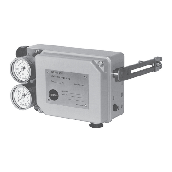
- Page 1 Electropneumatic Positioner Type 4763 Fig. 1 · Type 4763 Mounting and Operating Instructions EB 8359-2 EN Edition September 2010...
-
Page 2: Table Of Contents
Contents Contents Design and principle of operation ....6 Attachment ....... 8 Attachment to valves with cast yokes . - Page 3 Safety instructions General safety instructions The positioner is to be mounted, started up or operated only by trained and experienced personnel familiar with the product. According to these Mounting and Operating Instructions, trained personnel refers to individuals who are able to judge the work they are assigned to and recognize possible dangers due to their specialized training, their knowledge and experience as well as their knowledge of the applicable standards.
- Page 4 Versions Electropneumatic Positioner Type 4763- Explosion protection Without II 2 G EEx ia IIC T6 acc. to ATEX CSA/FM intrinsically safe/non incendive II 3 G EEx nA II T6 for Zone 2 (ATEX) Range spring Range spring 1, travel = 15 mm...
- Page 5 Technical data Type 4736 Positioner Travel range 7.5 to 60 mm, with 90 mm lever extension Reference variable 4 to 20 mA (Ex) Internal resistance R at 20 °C approx. 250 W ± 7 % Split-range 0 to 50 % 4 to 20 mA (not Ex) Internal resistance R at 20 °C approx.
-
Page 6: Design And Principle Of Operation
Design and principle of operation Design and principle of tional change of the air pressure p sent to the pneumatic control system. operation The air pressure p , in turn, produces a The electropneumatic positioner is used for force which acts on the surface of the mea- the correlation between the valve stem posi- suring diaphragm (8) and is compared to tion (controlled variable x) and the input sig-... - Page 7 Design and principle of operation Travel 10.2 10.1 Output 10.2 10.1 Supply Arrangement of nozzle/flapper for reverse <> operating direction 10.1 Nozzle Legend for Figs. 2 and 3 10.2 Flapper Range spring Lever for valve travel Cover plate Bracket Shaft Booster Mounting screw Xp restriction...
-
Page 8: Attachment
Attachment Attachment 2.1 Attachment to valves with cast yokes To attach the positioner to valves with cast yokes, mounting parts (order no. 1. Fasten the plate (20) to the stem connec- 1400-5745) are used. For valves with tor clamps (22) of the valve using the rod-type yokes (pillars), the mounting kit (or- screws (21). -
Page 9: Attachment To Valves With Rod-Type Yokes
Attachment 2.2 Attachment to valves with 4. Mount the positioner to the support using the mounting screw (15). Make sure that rod-type yokes the pin (2) is led inside the wire strap and therefore clamped against the plate 1. Screw the plate (20), off-centered, to the (20). -
Page 10: Connections
Connections Connections multi-core cables containing more than one intrinsically safe circuit. 3.1 Electrical connections In particular, the radial thickness of the con- ductor insulation for common insulation ma- DANGER! terials, such as polyethylene, must have a Risk of electric shock and/or the minimum radial thickness of 0.2 mm. -
Page 11: Pneumatic Connections
Connections 3.2.1 Pressure gauges We recommend attaching pressure gauges for the supply air and signal pressure in or- der to monitor the positioner. The parts are listed as accessories in the table on page Input control signal 3.2.2 Supply pressure (0)4 to 20 mA The required supply pressure is determined Fig. -
Page 12: Operation
Operation In the absence of such specifications, pro- identify the respective operating directions ceed as follows: (direct << or reverse <>). Required supply pressure = Depending on the flapper position, the ad- Upper bench range value + 1 bar justed operating direction is marked with the corresponding symbol. - Page 13 Operation Actuator: Stem extends (FA) p st p st Plate (20) on top of lever (1) Lever (1) on top of plate (20) Fig. 7 · Operating direction << Left attachment Fig. 8 · Operating direction <> Right attachment Actuator: Stem retracts (FE) p st p st Fig.
-
Page 14: Starting Point And Input Signal (Reference Variable)
Rated travel [mm] Min./max. travel [mm] Reference variable (input signal) Range spring Standard travels for SAMSON valves with lever I (40 to 127 mm long) 100 % 7.5 to 15 50 % 100 % 14 to 32... -
Page 15: Setting The Positioner At The Valve
Operation With a 4 to 20 mA input signal, for exam- ment screw (4) until the valve is at ap- ple, the valve must also move through the proximately 50 % valve travel. entire range (0 to 100 % ). The starting point On setting the Xp restriction, observe the re- then is 4 mA and the upper range value lationship with the supply air pressure as in-... -
Page 16: Setting Actuator Version "Stem Extends
Operation 4.3.2 Setting actuator version the valve!). If the upper range value is in- correct, the pin (2) must be moved as fol- “Stem extends” lows in order to correct the signal: 4. Move pin to: Note: End of lever –> to increase travel To ensure that the total closing force of the Pivot –>... -
Page 17: Exchanging The Range Spring
Operation 4.4 Exchanging the range spring Check if the valve begins to move at ex- actly 20 mA. If the range is to be altered or changed to Correct deviation using the zero adjust- split-range operation, replace the range ment screw (4); turning it counterclock- spring as shown in Fig. -
Page 18: Converting An Electropneumatic Into A Pneumatic Positioner
Converting an electropneumatic into a pneumatic positioner Converting an Required conversion kit for model index .03. electropneumatic into a or higher for G threaded connection pneumatic positioner Order number 1400-6795 The appropriate conversion kit allows the for NPT threaded connection electropneumatic positioner to be converted Order number 1400-6796 into a Type 4765 Pneumatic Positioner. -
Page 19: Servicing Explosion-Protected Devices
Servicing explosion-protected devices Maintenance, calibration and 4. Push the free end of the hose onto the connecting plate (6). work on equipment Servicing explosion-protected The interconnection with intrinsically safe devices circuits to check or calibrate the apparatus must only be performed with intrinsically If a part of the device on which the explo- safe current/voltage calibrators and mea- sion protection is based needs to be ser-... -
Page 20: Accessories And Mounting Parts
Accessories and mounting parts Accessories and mounting parts Accessories – Mounting parts Order number Range spring 1 1190-0736 Range spring 2 1190-0737 Range spring 3 1190-0738 Lever I 1690-6469 Lever extension 1400-6716 Pressure gauge attachment 1400-6950 Pressure gauge attachment, free of copper 1400-6951 Mounting kit for valves with cast yoke acc. -
Page 21: Dimensions In Mm
Dimensions in mm Dimensions in mm Useable lever length I: 40 to 127 mm (with 40 to 200 mm lever extension) Pneum. connection: ISO-228/1-G ¼ Cable gland Model index .02 or lower: PG 13.5 Model index .03 or higher: M 20 x 1.5 Tapped hole G for G threaded connection... -
Page 22: Test Certificates
EB 8359-2 EN... - Page 23 EB 8359-2 EN...
- Page 24 EB 8359-2 EN...
- Page 25 EB 8359-2 EN...
- Page 26 EB 8359-2 EN...
- Page 27 EB 8359-2 EN...
- Page 28 SAMSON AG · MESS- UND REGELTECHNIK Weismüllerstraße 3 · 60314 Frankfurt am Main · Germany Phone +49 69 4009-0 · Fax +49 69 4009-1507 EB 8359-2 EN Internet: http://www.samson.de...
Need help?
Do you have a question about the 4763 and is the answer not in the manual?
Questions and answers