Samson 4763 Mounting And Operating Instructions
Electropneumatic positioner
Hide thumbs
Also See for 4763:
- Mounting and operating instruction (78 pages) ,
- Mounting and operating instructions (56 pages) ,
- Mounting and operating instructions (28 pages)

Related Manuals for Samson 4763


Summary of Contents for Samson 4763
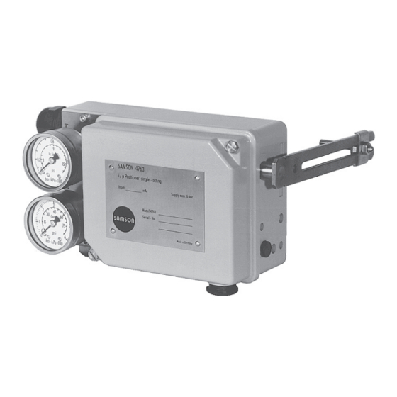
- Page 1 Electropneumatic Positioner Type 4763 Fig. 1 · Type 4763 Mounting and Operating Instructions EB 8359-2 EN Edition April 2008...
-
Page 2: Table Of Contents
Contents Contents Design and principle of operation ....6 Attachment....... 8 Attachment to valves with cast yokes. - Page 3 Proper shipping and appropriate storage are assumed. Note! The device with a CE marking fulfils the requirements of the Directives 94/9/EC (ATEX) and 89/336/EEC (EMC). The declaration of conformity can be viewed and downloaded on the Internet at http://www.samson.de. EB 8359-2 EN...
- Page 4 Versions Electropneumatic Positioner Type 4763- Explosion protection Without II 2 G EEx ia IIC T6 acc. to ATEX CSA/FM intrinsically safe/non incendive II 3 G EEx nA II T6 for Zone 2 acc. to ATEX Range spring Spring 1, travel = 15 mm...
- Page 5 Technical data Controlled variable (travel) 7.5 to 60 mm, with 90 mm lever extension at 20 °C approx. 250 Ω ± 7 % Reference variable 4 to 20 mA Ex Internal resistance R at 20 °C approx. 200 Ω ± 7 % 4 to 20 mA not Ex Internal resistance R Split-range 0 to 50 %...
-
Page 6: Design And Principle Of Operation
Design and principle of operation tional change of the air pressure p sent to Design and principle of the pneumatic control system. operation The air pressure p , in turn, produces a The electropneumatic positioner is used for force which acts on the surface of the mea- the correlation between the valve stem posi- suring diaphragm (8) and is compared to tion (controlled variable x) and the input sig-... - Page 7 Design and principle of operation Travel 10.2 10.1 Output 10.2 10.1 Supply Arrangement of nozzle/flapper for reverse <> operating direction Legends for Figs. 2 and 3 Lever for valve travel Range spring 10.1 Nozzle 1.1 Shaft 6.1 Bracket 10.2 Flapper Mounting screw Cover plate 2.1 Nut...
-
Page 8: Attachment
Attachment Attachment 2.1 Attachment to valves with cast yokes To attach the positioner to valves with cast yokes, mounting parts (order no. 1. Fasten the plate (20) to the stem connec- 1400-5745) are used. For valves with tor clamps (22) of the valve using the rod-type yokes (pillars), the mounting kit (or- screws (21). -
Page 9: Attachment To Valves With Rod-Type Yokes
Attachment 4. Mount the positioner to the support using 2.2 Attachment to valves with the mounting screw (15). Make sure that rod-type yokes the pin (2) is led inside the wire strap and therefore clamped against the plate 1. Screw the plate (20), off-centered, to the (20). -
Page 10: Connections
Connections Connections For EEx nL equipment (energy-limited apparatus), the standard EN 50021: 3.1 Electrical connections 1999 allows this type of equipment to be switched under normal operating conditions. For electrical installation, you are re- quired to observe the relevant electrotechnical regulations and the Caution! accident prevention regulations that The terminal assignment specified in the cer-... -
Page 11: Pneumatic Connections
Connections The wiring for the input signal is led using 3.2.2 Supply pressure cable glands to the terminals 11 (+) and 12 (–). The ground connection can be con- The required supply pressure is determined nected inside or outside of the positioner by the bench range and the operating direc- case. -
Page 12: Operation
Operation Depending on the flapper position, the ad- Operation justed operating direction is marked with the corresponding symbol. If the operating di- 4.1 Combining positioner and rection of the required function does not actuator match the symbol or if the operating direc- tion is to be changed, proceed as follows: The arrangement of the actuator, input sig- nal, operating direction and mounting loca-... - Page 13 Operation Actuator: Stem extends (FA) Lever (1) on top of plate (20) Plate (20) on top of lever (1) Fig. 7 · Operating direction << Left attachment Fig. 8 · Operating direction <> Right attachment Actuator: Stem retracts (FE) Fig. 9 · Operating direction << Right attachment Fig.
-
Page 14: Starting Point And Input Signal (Reference Variable)
Rated travel [mm] Min./max. travel Reference variable (input signal) Range spring [mm] Standard travels for SAMSON valves with lever l (40 to 127 mm long) 100 % 7.5 to 15 50 % 100 % 14 to 32 50 %... -
Page 15: Setting The Positioner At The Valve
Operation With a 4 to 20 mA input signal, for exam- adjustment screw (4) until the valve is at ple, the valve must also move through the approximately 50 % valve travel. entire range (0 to 100 % ). The starting On setting the X restriction, observe the re- point then is 4 mA and the upper range... -
Page 16: Setting Actuator Version "Stem Extends
Operation cator at the valve!). If the upper range 4.3.2 Setting actuator version value is incorrect, the pin (2) must be “Stem extends” moved as follows in order to correct the signal: Note! 4. Move pin to: To ensure that the total closing force of the End of lever –>... -
Page 17: Exchanging The Range Spring
Operation 2. Increase the input signal and slowly re- 4.4 Exchanging the range spring duce to a starting point of 20 mA again. Check if the valve begins to move at ex- If the range is to be altered or changed to actly 20 mA. -
Page 18: Conversion From Electropneumatic To Pneumatic Positioner
Conversion from electropneumatic to pneumatic positioner Conversion from Required conversion kit for model index .03. or higher electropneumatic to for G threaded connection pneumatic positioner Order number 1400-6795 The appropriate conversion kit allows the for NPT threaded connection electropneumatic positioner to be converted Order number 1400-6796 into a Type 4765 Pneumatic Positioner. -
Page 19: Servicing Explosion-Protected Devices
Servicing explosion-protected devices Servicing explosion-protected devices If a part of the positioner on which the ex- Explosion-protected components may only plosion protection is based needs to be ser- be replaced by original, checked compo- viced, the positioner must not be put back nents from the manufacturer. -
Page 20: Dimensions In Mm
Dimensions in mm Dimensions in mm Useable lever length I: 40 to 127 mm (with 40 to 200 mm lever extension) Pneum. connection: ISO-228/1-G ¼ Cable gland Model index .02 or lower: PG 13.5 Model index .03 or higher: M 20 x 1.5 Tapped hole G for case with G threaded connection... - Page 21 Dimensions in mm Rated travel [mm] Min./max. travel Reference variable (input signal) Range spring [mm] Standard travels for SAMSON valves with lever l (40 to 127 mm long) 100 % 7.5 to 15 50 % 100 % 14 to 32...
- Page 22 EB 8359-2 EN...
- Page 23 EB 8359-2 EN...
- Page 24 EB 8359-2 EN...
- Page 25 EB 8359-2 EN...
- Page 26 EB 8359-2 EN...
- Page 27 EB 8359-2 EN...
- Page 28 SAMSON AG · MESS- UND REGELTECHNIK Weismüllerstraße 3 · 60314 Frankfurt am Main · Germany Phone +49 69 4009-0 · Fax +49 69 4009-1507 EB 8359-2 EN Internet: http://www.samson.de...
Need help?
Do you have a question about the 4763 and is the answer not in the manual?
Questions and answers