
Subscribe to Our Youtube Channel
Related Manuals for Samson 4785


Summary of Contents for Samson 4785
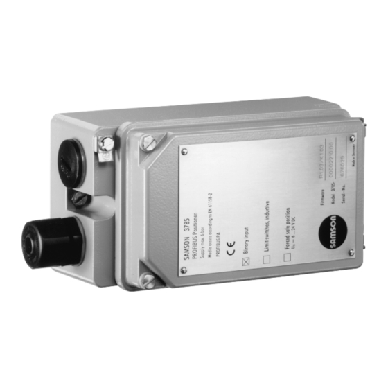
- Page 1 PROFIBUS Positioner Type 3785 PA device profile version 3.0 Fig. 1 ⋅ Type 3785 Mounting and operating instructions EB 8382-2 EN Firmware R 1.42/K 2.11 Edition January 2003...
- Page 2 Contents EB 8382-2 EN...
- Page 3 Contents EB 8382-2 EN...
- Page 4 Proper shipping and appropriate storage are assumed. Note! The device with a CE marking fulfils the requirements of the Directives 94/9/EC (ATEX) and 89/336/EEC (EMC). The declaration of conformity can be viewed and downloaded on the Internet at http://www.samson.de. EB 8382-2 EN...
- Page 5 Firmware modifications EB 8382-2 EN...
- Page 6 Firmware modifications EB 8382-2 EN...
- Page 7 Firmware modifications EB 8382-2 EN...
- Page 8 Technical data ≤ ∆ ∆ ∆ ∆ ≤ Ω Ω ≥ EB 8382-2 EN...
- Page 9 Versions EB 8382-2 EN...
- Page 10 Design and principle of operation EB 8382-2 EN...
- Page 11 Design and principle of operation 61158-2 µC PROFIBUS-PA µC Serial Interface Fig. 2 ⋅ Functional diagram EB 8382-2 EN...
- Page 12 Attaching the positioner For selection of the required mounting parts, refer to Tables 1, 2 and 3 on page 15. Note! The positioner does not have its own vent plug. The air is exhausted via vent plugs lo- cated on the accessories (also see Figs. 3, 5 and 7).
- Page 13 Attaching the positioner Fig. 3 ⋅ Attachment and signal pressure connection for Types 3277 (top) and 3277-5 Actuators with 120 cm (bottom) EB 8382-2 EN...
- Page 14 Attaching the positioner Note! If, in addition to the positioner, a solenoid valve or a similar device is attached to the 120 cm actuator, the rear M3 screw must not be removed. In this case, the signal pres- sure has to be fed from the signal pressure output to the actuator via the required con- necting plate (see Table 2).
- Page 15 Attaching the positioner Note! The new actuators (index 01) can only be used with new switchover and connecting plates. Old and new plates are not interchangeable. EB 8382-2 EN...
- Page 16 Attaching the positioner For selection of the required mounting parts, refer to Tables 4 and 5 on page 19. Note! Before you mount the parts, apply a signal pressure to the actuator so that the valve is set to 50 % of its travel. This will ensure the exact alignment of the lever (18) and the bracket (28).
- Page 17 Attaching the positioner 24 25 21 20 Fig. 4 ⋅ Attachment according to IEC 60534-6 (NAMUR) EB 8382-2 EN...
- Page 18 Attaching the positioner EB 8382-2 EN...
- Page 19 Attaching the positioner EB 8382-2 EN...
- Page 20 Attaching the positioner For selection of the required mounting parts, refer to Table 6 on page 23. EB 8382-2 EN...
- Page 21 Attaching the positioner 41 40 39 0˚ Fig. 5 ⋅ Attachment to rotary actuators EB 8382-2 EN...
- Page 22 Attaching the positioner In actuators with fail-safe position "Control valve open" (OPEN), the actuator must therefore be loaded with the max. signal pressure prior to aligning the cam disk. In springless actuators, the supply air must be connected. Note! With the valve closed, the starting point (bore hole) of the respective characteristic is to be aligned so that the center of rotation of the cam disk, the 0°...
- Page 23 Attaching the positioner Fig. 6 ⋅ Aligning the cam disk EB 8382-2 EN...
- Page 24 Reversing amplifier for double-acting actuators → Note! If the fail-safe position of the actuator is changed subsequently by modifying the ac- tuator springs from "Actuator stem extends" to "Actuator stem retracts", the mechanical zero point must be readjusted and the posi- tioner must be initialized again.
- Page 25 Reversing amplifier for double-acting actuators Output 38 Supply 9 1.3 1.2 Fig. 7 ⋅ Attaching a reversing amplifier EB 8382-2 EN...
- Page 26 Connections Note! The supply air must be dry and free of oil 2...3mm and dust. The maintenance instructions for upstream pressure reducing stations must be adhered to. Carefully purge all air tubes and hoses before connecting them. Fig. 8 ⋅ Mounting the pressure gauge EB 8382-2 EN...
- Page 27 Connections For electrical installation, you are re- quired to observe the relevant elec- trotechnical regulations and the acci- dent prevention regulations that apply in the country of use. In Germany, these are the VDE regu- lations and the accident prevention regulations of the employers’...
- Page 28 Connections Note on selecting the cables and wires: If you are routing several intrinsi- cally safe circuits in one multi-core cable, you are required to observe paragraph 12 of EN 60079-14 and VDE 0165/8.98. Note especially that for commonly used insulation materials, such as polyethylene, the radial thickness of the conductor insulation must be at least 0.2 mm.
- Page 29 Connections Note! The connection of limit switches, binary input and forced venting function requires Caution! an additional cable gland which must re- If no voltage is connected or when the volt- place the cap fitted on the housing. age signal is interrupted, the positioner Accessories: Cable gland M20 x 1.5, nickel- vents the actuator and does not respond to plated brass, order no.
- Page 30 Connections Note! A new bus address is not accepted, unless you perform a new start-up of the device. Note! Addressing via microswitch is given priority over a software-adjusted bus address. EB 8382-2 EN...
- Page 31 Connections PROFIBUS-DP(E) RS 485 (Class Master) (Class 2 Master) PROFIBUS-DP(E) RS 485 Termination PROFIBUS-PA IEC 61158-2 Termination 3785 3785 3785 3785 Ï Ð PROFIBUS-DP RS 485 (Class 2 Master) (Class Master) PROFIBUS-DP RS 485 Termination PROFIBUS-PA IEC 61158-2 3785-1 3785-1 3785-1 3785-1 Termination...
- Page 32 Operation Warning! Before putting the positioner into operation, carefully move the con- trol valve to its final position by covering the hole (manual oper- ation) on the cover plate (Fig. 11). Check whether the lever mechanism functions properly. If the maximum angle of rotation is exceeded by selecting the wrong lever mechanism or by sizing the mechanism improperly, the posi-...
- Page 33 Operation Note! Manual operation and activated final position functions can cause the actuator to be filled with the maximum supply pressure. Should this lead to impermissible forces occurring, the supply pressure must be restricted by a suitable re- ducing station. Fig.
- Page 34 Operation during the start-up cycle when the shut-off valves in the plant are closed, or when the control valve Note! with the positioner has been Zero must be adjusted with the valve closed removed from the plant and is used (for three-way valves with the actuator stem on a test stand.
- Page 35 Operation Caution! The control valve moves to its final position. Note! After the positioner has been initialized suc- cessfully for the first time, pressing the Init/Zero key only starts a zero calibration. EB 8382-2 EN...
- Page 36 Adjusting the inductive limit switches EB 8382-2 EN...
- Page 37 Maintenance µ EB 8382-2 EN...
- Page 38 How to implement the PROFIBUS Master Class 1 EB 8382-2 EN...
- Page 39 How to implement the PROFIBUS Master Class 1 EB 8382-2 EN...
- Page 40 How to implement the PROFIBUS Master Class 1 EB 8382-2 EN...
- Page 41 How to implement the PROFIBUS Master Class 1 EB 8382-2 EN...
- Page 42 How to implement the PROFIBUS Master Class 1 EB 8382-2 EN...
- Page 43 How to implement the PROFIBUS Master Class 1 EB 8382-2 EN...
- Page 44 How to implement the PROFIBUS Master Class 1 EB 8382-2 EN...
- Page 45 How to implement the PROFIBUS Master Class 1 EB 8382-2 EN...
- Page 46 How to implement the PROFIBUS Master Class 1 EB 8382-2 EN...
- Page 47 How to implement the PROFIBUS Master Class 1 EB 8382-2 EN...
- Page 48 How to implement the PROFIBUS Master Class 1 EB 8382-2 EN...
- Page 49 EB 8382-2 EN...
- Page 50 EB 8382-2 EN...
- Page 51 List of parameters EB 8382-2 EN...
- Page 52 List of parameters EB 8382-2 EN...
- Page 53 List of parameters EB 8382-2 EN...
- Page 54 List of parameters EB 8382-2 EN...
- Page 55 List of parameters EB 8382-2 EN...
- Page 56 List of parameters EB 8382-2 EN...
- Page 57 List of parameters EB 8382-2 EN...
- Page 58 List of parameters − EB 8382-2 EN...
- Page 59 List of parameters EB 8382-2 EN...
- Page 60 List of parameters EB 8382-2 EN...
- Page 61 List of parameters EB 8382-2 EN...
- Page 62 List of parameters ≥ ≥ ≥ EB 8382-2 EN...
- Page 63 List of parameters EB 8382-2 EN...
- Page 64 List of parameters EB 8382-2 EN...
- Page 65 List of parameters EB 8382-2 EN...
- Page 66 Messages and diagnosis ± EB 8382-2 EN...
- Page 67 Messages and diagnosis EB 8382-2 EN...
- Page 68 Messages and diagnosis EB 8382-2 EN...
- Page 69 Messages and diagnosis EB 8382-2 EN...
- Page 70 Messages and diagnosis EB 8382-2 EN...
- Page 71 Messages and diagnosis ± − − − − EB 8382-2 EN...
- Page 72 Dimensional diagram M20 x1.5 Output (38) 30.5 Supply (9) Output 1 (A1) 28.5 Output 2 (A2) Supply (Z) EB 8382-2 EN...
- Page 73 EB 8382-2 EN...
- Page 74 EB 8382-2 EN...
- Page 75 EB 8382-2 EN...
- Page 76 EB 8382-2 EN...
- Page 77 EB 8382-2 EN...
- Page 78 ⋅ ⋅ ⋅ ⋅...
Need help?
Do you have a question about the 4785 and is the answer not in the manual?
Questions and answers